1.
2.
3.
4.
2x M4x8
74
75
76
77
Assembly
4
Install the PE1 Pellet Unit
Installation Instructions PE1 Pellet 7-35 | M1441017_en
55
Страница 1: ...riginal German installation instructions for technicians Read and follow the instructions and safety information Technical changes typographical errors and omissions reserved M1441017_en Edition 24 03...
Страница 2: ...lation room 15 2 4 10 Note on installing an external combustion air supply 15 2 4 11 Simultaneous operation with other air drawing systems room ventilation cooker hood centralised dust extraction syst...
Страница 3: ...Install boiler filling and drainage system 50 4 7 7 Expansion with pipe assembly for storage loading 51 4 7 8 Expansion with pump assembly for second heating circuit 53 4 7 9 Disassemble for easier tr...
Страница 4: ...differences from the pictures and content If you discover any errors please let us know doku froeling com Subject to technical change The EC Declaration of Conformity is only valid in conjunction with...
Страница 5: ...erved it will lead to serious injury or death You must follow the instructions WARNING The dangerous situation may occur and if measures are not observed it will lead to serious injury or death Work w...
Страница 6: ...equipment specified by accident prevention regulations For transportation setup and assembly suitable work wear protective gloves sturdy shoes min protection class S1P 2 4 Design Information 2 4 1 No...
Страница 7: ...sion and scale formation in closed warm water heating systems at operating temperatures up to 100 C Austria VDI 2035 Prevention of damage hot water heating systems Germany SWKI BT 102 01 Water quality...
Страница 8: ...t provide any light so the customer must ensure sufficient lighting in the boiler room in accordance with national workplace design regulations When using the boiler above 2000 metres above sea level...
Страница 9: ...alue must be between 8 0 and 8 5 Use prepared water which complies with the standards cited above for filling and makeup water Avoid leaks and use a closed heating system to maintain water quality dur...
Страница 10: ...in certain conditions If some of the system water is lost e g during repairs the make up water must also be demineralised It is not enough to soften the water The heating system must be professionally...
Страница 11: ...The valve releases hot water into the receiving tank if the pressure is too high If the pressure drops below a preset value the pump draws water from the receiving tank and feeds it back into the hea...
Страница 12: ...h a way that is poses no risk to persons Draught limiter We generally recommend the installation of a draught limiter A draught limiter must be installed if the maximum permissible feed pressure as gi...
Страница 13: ...load m h 14 20 29 39 1 optional flue gas diameter of 129 mm without additional connecting adapter possible Description PE1 Pellet 25 30 32 35 Flue gas temperature at nominal load C 140 150 160 160 Flu...
Страница 14: ...at similar wind conditions apply NOTICE Air is supplied by an air and flue gas system A boiler that is connected via its combustion air supply and flue gas outlet with a connecting piece to a wind pro...
Страница 15: ...ion air to the installation room Observe the following at the combustion air opening leading outside Weather conditions must not affect the air flow in any way e g snow and foliage The free cross sect...
Страница 16: ...ional requirement must be observed The lines must be installed with an incline making sure that any condensation water can drain away and the outside air can be drawn in without allowing water or anim...
Страница 17: ...operating with the window closed A drive systems tilts the window open when air drawing systems e g 3 or 4 are in operation This prevents a reversal of the combustion gas flow in the chimney and thus...
Страница 18: ...ously with a room air dependent appliance the room side under pressure must not exceed 4 Pa In addition at least one of the following three requirements must be met Source Section 4 MFeuV 2007 2010 Us...
Страница 19: ...stall external combustion air supply Use safety systems e g an under pressure monitoring system window tilting drive system or window tilting switch etc Recommendation for room ventilation systems Use...
Страница 20: ...1200 1200 1470 H1 Height of flue pipe connection 940 940 1170 H2 Height of flow connection 930 930 1160 H3 Height of return connection 750 750 920 H4 Height of drainage connection 95 95 175 H5 Height...
Страница 21: ...flow return connection of the boiler 710 710 H5 Height of the drainage connection of the boiler 690 690 H6 Height of the hot water circulation connection of the boiler block 350 350 H7 Height of the c...
Страница 22: ...nnection 1 2 IT 4 Supply air connection external diameter mm 80 100 5 Flue gas pipe connection 99 1 129 149 6 Pellet suction line connection 50 7 Return air line connection 50 1 optional flue gas diam...
Страница 23: ...circuit group 1 IT 6 Line regulating valve 7 Safety group with pressure gauge for system pressure quick vent valve and safety valve 8 Expansion tank in hydraulic block Litres 18 24 9 Connection hot w...
Страница 24: ...3 3 Permitted operating pressure domestic hot water 6 6 Test over pressure domestic hot water 9 9 Minimum boiler return temperature Not applicable due to internal return temperature control Maximum bo...
Страница 25: ...3 69 Organic hydrocarbons OGC mg MJ 1 0 1 0 1 0 1 0 Dust mg MJ 10 3 4 0 11 2 4 0 Boiler efficiency 94 3 90 9 94 5 90 9 1 The pollutant concentration is specified as a mass based on the energy content...
Страница 26: ...ure control Maximum boiler temperature setting C 90 Minimum boiler temperature setting 40 Permitted operating temperature 95 Permitted operating temperature domestic hot water 110 Airborne sound level...
Страница 27: ...mass based on the energy content of the fuel fed to the combustion system in mg MJ Test data Emissions in mg m 1 nominal load partial load Carbon monoxide CO mg m 17 17 15 17 Nitrogen oxide NOx mg m 1...
Страница 28: ...er temperature setting C 90 Minimum boiler temperature setting 50 Airborne sound level dB A 70 Boiler class as per EN 303 5 2012 5 Permitted fuel Fuel acc to EN ISO 17225 Part 2 Wood pellets class A1...
Страница 29: ...mass based on the energy content of the fuel fed to the combustion system in mg MJ Test data Emissions in mg m 1 nominal load partial load Carbon monoxide CO mg m 14 18 16 18 Nitrogen oxide NOx mg m 1...
Страница 30: ...iler temperature setting C 90 Minimum boiler temperature setting 50 Airborne sound level dB A 70 Boiler class as per EN 303 5 2012 5 Permitted fuel Fuel acc to EN ISO 17225 Part 2 Wood pellets class A...
Страница 31: ...mass based on the energy content of the fuel fed to the combustion system in mg MJ Test data Emissions in mg m 1 nominal load partial load Carbon monoxide CO mg m 16 18 17 18 Nitrogen oxide NOx mg m 1...
Страница 32: ...suction module 220 265 H1 Height of suction module 225 235 H2 Total height incl hose connection 275 285 1 Return air line connection line to suction point mm 50 2 Return air line connection line to b...
Страница 33: ...end the use of a plier wrench for the flat sealing joints of the PE1 Pellet Unit Cordless screwdriver and set of Torx bits T20 T25 T30 Power drill with masonry drill bit 12 mm 4 2 Transport The produc...
Страница 34: ...llation site page 57 Use a crane to transport to transport to installation site only wit PE1 Pellet 2 3 3 4 4 4 Temporary storage If the system is to be assembled at a later stage Store components at...
Страница 35: ...ey should be observed in addition to the specified minimum distances Observe the applicable standards and regulations when setting up the system Observe additional standards for noise protection NORM...
Страница 36: ...side of boiler to wall controller side 300 mm C Distance back to wall D Distance side of boiler to wall door stop side 100 mm Minimum space length x width mm 1750 x 1000 1750 x 1150 H Minimum room hei...
Страница 37: ...the boiler on the floor page 40 See Prepare for room air independent operation page 42 See Installing the discharge system page 60 See Install the protective plate for the flue pipe page 62 See Hydra...
Страница 38: ...he boiler comes bolted to a pallet and must be removed as follows PE1 Pellet 7 20 PE1 Pellet 25 35 2x 2x 2x 2x 1x 1x 4 5 6 4 5 6 4 Assembly Install PE1 Pellet 38 Froling GesmbH A 4710 Grieskirchen Ind...
Страница 39: ...boiler size PE1 Pellet 25 the following steps are necessary for the transport and for the subsequent alignment of the adjustable feet 1x M4x8 2x M5x10 2x M4x8 3x M5x10 7 8 9 10 11 12 Assembly 4 Insta...
Страница 40: ...gned on the floor Different approaches are required depending on the boiler size PE1 Pellet 7 20 For the PE1 Pellet 7 20 the adjustable feet are easily accessible with tools from outside 15 4 Assembly...
Страница 41: ...positioning of the boiler Remove the insulated door and cover plate See PE1 Pellet 25 35 Prepare the boiler for transport and setup page 39 The adjustable feet are accessible after removing the floor...
Страница 42: ...operation With the following modifications the PE1 Pellet can be operated independently of the room air 4x M4x8 4x M4x8 17 18 19 4 5 6 4 Assembly Install PE1 Pellet 42 Froling GesmbH A 4710 Grieskirch...
Страница 43: ...tridge page 49 See Install boiler filling and drainage system page 50 See Expansion with pipe assembly for storage loading page 51 See Expansion with pump assembly for second heating circuit page 53 S...
Страница 44: ...let The Unit comes bolted to a pallet and must be removed as follows 1 1 2 2 4x 5x60 8x 5x40 4x M10 20 21 22 23 5 6 4 Assembly Install the PE1 Pellet Unit 44 Froling GesmbH A 4710 Grieskirchen Industr...
Страница 45: ...he Unit has been positioned and aligned the front cover must be fitted as follows 2x M5x10 2x M5x10 2x M5x10 2x M5x10 24 25 26 27 28 29 Assembly 4 Install the PE1 Pellet Unit Installation Instructions...
Страница 46: ...er must be aligned on the floor The PE1 Pellet 7 20 Unit comes without adjusting feet and must be positioned using the boiler underlays provided 4x 30 4 Assembly Install the PE1 Pellet Unit 46 Froling...
Страница 47: ...7 20 can be operated independently of the room air This requires an optional connection set which is installed as follows Variant 1 Rear connection 4x M4x8 2x M4x8 1 2 31 32 33 34 35 36 Assembly 4 In...
Страница 48: ...Variant 2 Top connection 4x M4x8 2x M4x8 1 2 37 38 39 40 41 42 4 Assembly Install the PE1 Pellet Unit 48 Froling GesmbH A 4710 Grieskirchen Industriestra e 12 www froeling com...
Страница 49: ...ck of the PE1 Pellet 7 20 Unit can be fitted with an electronic heating cartridge This requires the following modifications 2x M5x10 2x M5x10 60 80Nm 43 44 45 46 47 48 Assembly 4 Install the PE1 Pelle...
Страница 50: ...f the PE1 Pellet 7 20 Unit in a controlled manner we recommend the installation of a boiler filling and drainage system It is mounted as follows to the lowest part of the boiler 51 4 Assembly Install...
Страница 51: ...connected to the PE1 Pellet Unit an optional pipe assembly for storage loading is required This requires the following modifications 1 2 3 4 2x M4x8 2x 30x2 1 2 52 53 54 55 56 57 Assembly 4 Install t...
Страница 52: ...P2 6 3A T Hydraulikmodul FRHYU 21 FRHYU AO P1 Pumpe 1 L N 1 2 1 2 3 4 2x M4x8 58 59 60 61 5 6 4 Assembly Install the PE1 Pellet Unit 52 Froling GesmbH A 4710 Grieskirchen Industriestra e 12 www froel...
Страница 53: ...c block can be expanded with an optional pump assembly for a second heating circuit This requires the following modifications 2x M5x10 2x M5x10 2x M5x10 1 2 1 2 62 63 64 65 66 67 Assembly 4 Install th...
Страница 54: ...4x M8x20 2x M8 2x M8x20 68 69 70 71 72 73 4 Assembly Install the PE1 Pellet Unit 54 Froling GesmbH A 4710 Grieskirchen Industriestra e 12 www froeling com...
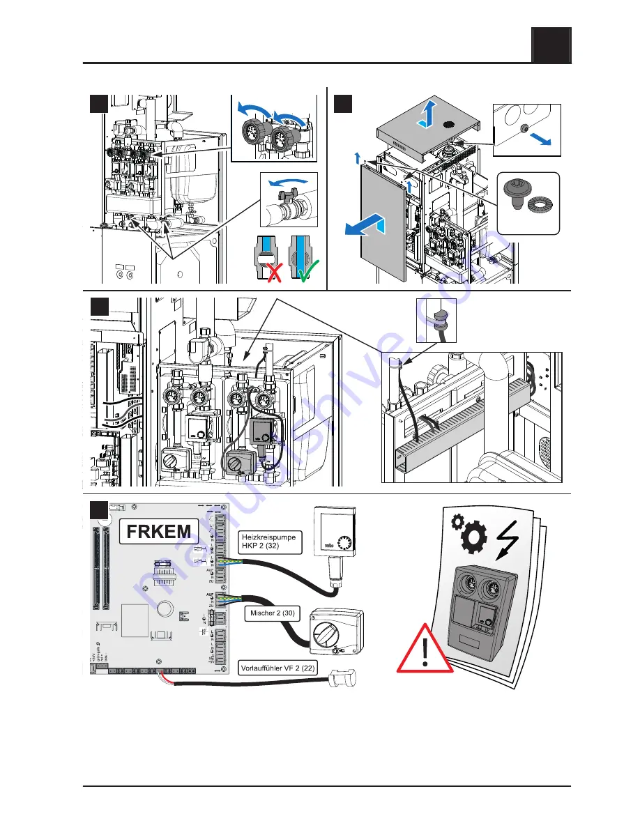
Страница 55: ...1 2 3 4 2x M4x8 74 75 76 77 Assembly 4 Install the PE1 Pellet Unit Installation Instructions PE1 Pellet 7 35 M1441017_en 55...
Страница 56: ...4 3 2 1 2x M4x8 4x M5x10 2 1 1 2 78 79 80 81 5 6 4 Assembly Install the PE1 Pellet Unit 56 Froling GesmbH A 4710 Grieskirchen Industriestra e 12 www froeling com...
Страница 57: ...of the PE1 Pellet Unit prevents it from being transported as a single unit it can be disassembled as follows into its individual components 1 2 3 4 2x M4x8 4x M4x8 1 2 82 83 84 85 86 Assembly 4 Instal...
Страница 58: ...3A T Hydraulikmodul FRHYU 21 FRKEM FRHYU VF1 Vorlauf f hler HKP 1 Heizkreis pumpe Mischer 1 Netz Pumpe 2 AO P2 87 88 4 Assembly Install the PE1 Pellet Unit 58 Froling GesmbH A 4710 Grieskirchen Indus...
Страница 59: ...x10 89 90 91 92 5 6 Once they have been transported to the installation room they can be re assembled in reverse order Assembly 4 Install the PE1 Pellet Unit Installation Instructions PE1 Pellet 7 35...
Страница 60: ...upplied assembly material is suitable and if required needs to be replaced by suitable material for the base No specific installation position is required for the suction turbine to operate smoothly P...
Страница 61: ...12 mm 12 mm 3x 6x45 3x 12x45 8x M6x20 93 94 95 96 97 98 Assembly 4 Installing the discharge system Installation Instructions PE1 Pellet 7 35 M1441017_en 61...
Страница 62: ...or the flue pipe To prevent contact with the components of the hot flue pipe a protective plate must be fitted as follows to the rear boiler wall 4 Assembly Install the protective plate for the flue p...
Страница 63: ...aulic connection must be fitted by the customer in such a way that the cover B can be easily unscrewed A and removed Keep the maintenance area toward the back clear Assembly 4 Hydraulic connection Ins...
Страница 64: ...of electrocution When work is carried out on electrical components Only have work carried out by a qualified electrician Observe the applicable standards and regulations Work must not be carried out...
Страница 65: ...control line is connected to the corresponding PDM outputs of the boards Observe the connection instructions in the boiler controller documentation CAUTION When using high efficiency pumps without an...
Страница 66: ...ng filled Fill the domestic water tank with cold drinking water Check that all connections on the drinking water side are tight Check the safety valve on the cold water supply line is in good working...
Страница 67: ...0 Turn on the main switch Set the boiler controller to the system type Load the boiler default values NOTICE For the keypad layout and instructions for modifying the parameters see the instruction man...
Страница 68: ...rained by a qualified technician Protection against frost 6 2 Disassembly To disassemble the system follow the steps for assembly in reverse order 6 3 Disposal Ensure that they are disposed of in an e...
Страница 69: ...izkessel und Beh lterbau GesmbH Industriestra e 12 A 4710 Grieskirchen AUSTRIA TEL 0043 0 7248 606 0 FAX 0043 0 7248 606 600 INTERNET www froeling com 7 1 2 Address of the installer Stamp Appendix 7 A...