Step 1
Step 2
Figure 3
Figure 1
Figure 2
Step 3
Step 4
Step 5
Step 6
Figure 4
Figure 5
Figure 6
Figure 7
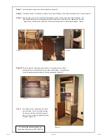
Lay the header assembly in place and align the holes
so that you can push the last two 1/4-20 x 2" screws
through the side frames and tighten into the header.
Tighten with a phillips screw driver (figure 7)
Locate the left side frame, the steel back support,
and 4 of the 1/4-20 x 2" phillips truss head screws.
Begin assembly by laying the back support and the
left frame out as shown (figure 1)
Align the holes in the steel back support with the
through holes in the side frame and insert the
screws. Tighten with a phillips screwdriver (figure
2). Repeat with the right frame (figure 3).
Install the 2 back levelers into the bottoms of the
left and right frames. (figure 4)
Attach the two microwave support angles to each
end. Push the 1/4-20 x 5/8 truss head screw
through the slot in the bracket and screw it into the
insert on the end.
Do not fully tighten at this time.
(Figure 6)
Insert the 2 front levelers through the hole in the
anti-tip strap then screw them into the holes in the
bottom of the right and left Frame. (figure 5)
If you have any questions, please call:
Black River Display Group (419) 524.2000
954133
Page 2 of 3
03/2015


