background image

3

30" GAS SLIDE-IN RANGE INSTALLATION INSTRUCTIONS

(Models with Sealed Top Burners)

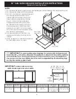
Important Notes to the Installer

1.  Read all instructions contained in these installation 

instructions before installing range.

2.  Remove all packing material from the oven 

compartments before connecting the gas and 
electrical supply to the range.

3.  Observe all governing codes and ordinances.
4.  Be sure to leave these instructions with the consumer.
5.  Note: For operation at 2000 ft. elevations above see 

level, appliance rating shall be reduced by 4 percent 
for each additional 1000 ft.

Important Note to the Consumer

Keep these instructions with your Use & Care Guide for 
future reference.

IMPORTANT SAFETY 
INSTRUCTIONS

Installation of this range must conform with local codes 
or, in the absence of local codes, with the National Fuel 
Gas Code ANSI Z223.1/NFPA .54-latest edition.
This range has been design certified by CSA 
International. As with any appliance using gas and 
generating heat, there are certain safety precautions you 
should follow. You will find them in the Use and Care 
Guide, read it carefully.

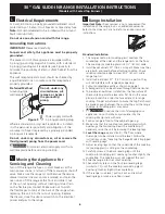
 Be sure your range is installed and grounded 

properly by a qualified installer or service 
technician.

• 

This range must be electrically grounded in 
accordance with local codes or, in their absence, 
with the National Electrical Code ANSI/NFPA No. 
70—latest edition.

 See Grounding Instructions.

• 

Before installing the range in an area covered with 
linoleum or any other synthetic floor covering, 
make sure the floor covering can withstand heat 
at least 90°F above room temperature without 
shrinking, warping or discoloring.

 Do not install the 

range over carpeting unless you place an insulating pad 
or sheet of ¼" (10,16 cm) thick plywood between the 
range and carpeting.

•  Air  curtain  or  other  overhead  hoods,  which  operate  by 

blowing a downward air flow on to a range, shall not be 

used in conjunction with gas ranges other than when the 

hood  and  range  have  been  designed,  tested  and  listen 

by an independent test laboratory for use in combination 

with each other.

• 

Make sure the wall coverings around the range 
can withstand the heat generated by the range.

• 

Do not obstruct the flow of combustion air at the 
oven vent nor around the base or beneath the 
lower front panel of the range. 

Avoid touching the 

vent openings or nearby surfaces as they may become 
hot while the oven is in operation. This range requires 
fresh air for proper burner combustion.

 Never leave children alone or 

unattended in the area where an appliance is in 
use. 

As children grow, teach them the proper, safe use 

of all appliances. Never leave the oven door open when 
the range is unattended.

 Stepping, leaning or sitting on the 

doors or drawers of this range can result in serious 
injuries and can also cause damage to the range.

• 

Do not store items of interest to children in 
the cabinets above the range. 

Children could be 

seriously burned climbing on the range to reach items.

• 

To eliminate the need to reach over the surface 
burners, cabinet storage space above the burners 
should be avoided.

• 

Adjust surface burner flame size so it does not 
extend beyond the edge of the cooking utensil.


Excessive flame is hazardous.

• 

Do not use the oven as a storage space. 

This 

creates a potentially hazardous situation.

• 

Never use your range for warming or heating the 
room. 

Prolonged use of the range without adequate 

ventilation can be dangerous.

• 

Do not store or use gasoline or other flammable 
vapors and liquids near this or any other 
appliance. 

Explosions or fires could result.

• In the event of an electrical power outage, the surface 

burners can be lit manually. To light a surface burner, 
hold a lit match to the burner head and slowly turn 
the Surface Control knob to LITE. Use caution when 
lighting surface burners manually.

• 

Reset all controls to the "off" position after using 
a programmable timing operation.

FOR MODELS WITH SELF-CLEAN FEATURE:

• 

Remove broiler pan, food and other utensils 
before self-cleaning the oven. 

Wipe up excess 

spillage. Follow the precleaning instructions in the Use 
and Care Guide.

• 

Unlike the standard gas range, THIS COOKTOP 
IS NOT REMOVABLE. 

Do not attempt to remove the 

cooktop.


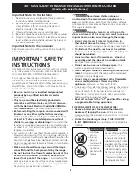
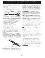
To reduce 

the risk of tipping of the 
range, the range must 
be secured by properly 
installed anti-tip bracket 
provided with the range. 
To check if the bracket is 
installed properly, grasp 
the top rear edge of the 
range and carefully tilt 
it forward to make sure 
the range is anchored.

•  All ranges 

can tip.

•  Injury to 

persons 
could result.

•  Install anti-

tip device 
packed with 
range.

Содержание Electric Slide-In Range

Страница 1: ...closed in this booklet Printed in United States Appliances Installed in the state of Massachusetts This Appliance can only be installed in the state of Massachusetts by a Massachusetts licensed plumber or gasfitter This appliance must be installed with a three 3 foot 36 in long flexible gas connector A T handle type manual gas valve must be installed in the gas supply line to this appliance Refer ...

Страница 2: ...atch the cutout width E E 21 55 25 cm D C A B Door Open see note 5 Side panel A HEIGHT B WIDTH C COOKTOP WIDTH D DEPTH TO FRONT OF RANGE E CUTOUT WIDTH Countertop and Cabinet F CUTOUT DEPTH G HEIGHT OF COUNTERTOP 35 5 8 90 5 cm 36 5 8 93cm 30 76 2 cm 31 80 cm 28 5 16 71 9 cm 30 1 16 76 2 0 15 cm 21 3 4 55 2 cm Min 22 1 8 56 2 cm Max 24 61 cm Min with backguard 36 5 8 93 cm Max 35 5 8 90 5 cm Min 3...

Страница 3: ...ow of combustion air at the oven vent nor around the base or beneath the lower front panel of the range Avoid touching the vent openings or nearby surfaces as they may become hot while the oven is in operation This range requires fresh air for proper burner combustion Never leave children alone or unattended in the area where an appliance is in use As children grow teach them the proper safe use o...

Страница 4: ...st be at least 11 27 9 cm Leak testing of the appliance shall be conducted according to the instructions in step 4 The gas supply line should be or I D Interior Diameter 3 Seal the openings Seal any openings in the wall behind the range and in the floor under the range after gas supply line is installed 1 Cabinet Construction To eliminate the risk of cabinet burns and fire do not have cabinet stor...

Страница 5: ...e testing of the gas supply piping system at test pressures equal to or less than 1 2 psig 3 5 kPa or 14 water column 5 LP Propane Gas Conversion This appliance can be used with Natural gas or LP Propane gas It is shipped from the factory for use with natural gas If you wish to convert your range for use with LP Propane gas use the supplied fixed orifices located in a bag containing the literature...

Страница 6: ... conduit Make sure not to pinch the flexible gas conduit at the back of the range when replacing the unit into the cut out opening Replace the drawer close the door and switch on the electrical power and gas to the range Standard Installation 1 The range cooktop or cooktop glass overlaps the countertop at the sides and the range rests on the floor The cooktop or cooktop glass is 31 81 cm wide 2 In...

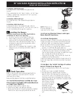
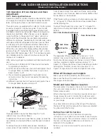
Страница 7: ...th sealed burners as shown see Figure 7 a Unpack burner bases and burner caps b Place burner bases over each gas opening c Make sure the burner is properly aligned and leveled Place burner caps over appropriate burner bases 10 2 Turn on Electrical Power and Open Main Shutoff Gas Valve 10 3 Check the Igniters Operation of electric igniters should be checked after range and supply line connectors ha...

Страница 8: ...ven Burner front of oven bottom from oven front frame and pull the oven bottom out of the oven Remove burner baffle so that burner flame can be observed If the flame is yellow increase air shutter opening size see 2 in Figure 10 If the entire flame is blue reduce the air shutter opening size To adjust frame loosen lock screw see 3 in Figure 10 reposition air shutter and tighten lock screw Replace ...

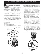
Страница 9: ...ip brackets 5 Slide range into place making sure rear legs are trapped by ends of brackets Range may need to be shifted slightly to one side as it is being pushed back to allow rear legs to slide under brackets You may also grasp the top rear edge of the range and carefully attempt to tilt it forward to make sure range is properly anchored 11 Anti Tip Brackets Installation Instructions To reduce t...

Страница 10: ...diagrama de cables de esta cocina al final de este libreta Aparatos Instalados en el estado de Massachusetts Este Aparato sólo puede ser instalado en el estado de Massachusetts por un plomero o ajustador de gas licenciado de Massachusett Este aparato se debe instalar con un largo conector flexible de gas de tres 3 pies 36 pulgadas Una válvula manual de gas de tipo manija de forma de T se debe inst...

Страница 11: ...93 cm 30 76 2 cm 28 5 16 71 9 cm 30 1 16 76 2 0 15 cm 21 3 4 55 2 cm Min 22 1 8 56 2 cm Max 24 61 cm Min con un protector trasero 36 5 8 93 cm Max 35 5 8 90 5 cm min 31 80 cm 21 55 25 cm D C A B Panel lateral Puerta abierta vea la nota 5 1 1 8 2 86 cm PARTE DELAN TERA DEL ARMARIO FRef 22 7 8 58 1 cm min 23 1 4 59 05 cm max nota 4 IMPORTANTE El ancho de la cubierta y el armario debe de ser igual al...

Страница 12: ...struya el flujo del aire de combustión en la ventilación del horno ni tampoco alrededor de la base o debajo del panel inferior delantero de la estufa Evite tocar las aberturas o áreas cercanas de la ventilación ya que pueden estar muy calientes durante el funcionamiento del horno La estufa requiere aire fresco para la combustión apropiada de los quemadores Nunca deje niños solos o desatendidos en ...

Страница 13: ...ulador se encuentra en el lugar que se muestra en la ilustración Figura 2 No permita que el regulador gire sobre la tubería al apretar las uniones Ubicación del regulador de presión Figura 2 1 9 cm 1 9 cm 31 81 cm 1 Construcción del armario Para eliminar el riesgo de quemaduras o de fuego tratando de alcanzar algo por encima de las zonas calientes evite de colocar artículos sobre la cocina Si cree...

Страница 14: ...versión para uso de Propano Líquido Este aparato puede ser usado con gas natural o propano líquido Ha sido ajustado en la fábrica para operar con gas natural solamente Si desea convertir su estufa para uso con propano líquido use los orificios provistos ubicados en el bolso que contiene la literatura titulada FOR LP PROPANE GAS CONVERSION Siga las instrucciones que vienen con los orificios La conv...

Страница 15: ...uerta y enciende el gas y la corriente eléctrica a la estufa 8 Instalación de la cocina Nota importante No es necesario pero sí es conveniente quitar la puerta para instalar el horno Consulte las instrucciones para retirar la puerta en la Guía de Uso y Cuidado Instalación estándar 1 La plancha de cocinar se sobrepone por encima del mostrador con sus extremidades y la cocina reposa sobre el suelo L...

Страница 16: ...emadores b Coloque una basa de quemador sobre cada abertura de gas c Asegúrese que el quemador está correctamente alineado y nivelado Coloque las tapas de los quemadores sobre las correctas basas de quemadores 10 2 Enciende la corriente eléctrica y abre la válvula principal de cierre 10 3 Comprobación de los Encendedores El funcionamiento de los encendedores eléctricos debe ser comprobado después ...

Страница 17: ... debe de encenderse Revise si exista una llama adecuada Gire los controles hacia off APAGADO 10 5 2 Obturador del Aire Quemador del horno La longitud aproximada de la llama del quemador del horno es 1 pulgada interior claro llama azul Para determinar si la llama del quemador de horno es la adecuada retire el fondo del horno y el deflector del quemador i fije el horno en la opción hornear a 300 F P...

Страница 18: ...ras estén sujetas por los extremos de los soportes La estufa puede necesitar ser movida ligeramente a un lado cuando está siendo Figura 11 Borde de atras de laestufa o pared trasera Soporte antivuelco Anchura trasera de la estufa con los lados Deslizar hacia atras Soporte antivuelco Antes de Llamar al Servicio Lea la sección Evite Llamadas de Servicio en su Manual del Usuario Esto le podrá ahorrar...

Страница 19: ... 2 cm du plancher MUR 5 Min 12 7 cm Min des deux côtés 18 Min 45 7 cm Min Approx 1 7 8 4 8 cm Installez les portes de l armoire à au moins 1 2 5 cm de l ouverture F G E 31 1 2 81 cm Exact 13 33 cm Arasez le dessus du comptoir à au moins 31 81 cm de largeur pour l appareil 1 Max 3 8 cm Max 30 Min 76 2 cm Min voir la note 3 24 Min 61 cm Min Ces surfaces doivent être planes et à niveau région hachuré...

Страница 20: ...16 71 9 cm 30 1 16 76 2 0 15 cm 21 3 4 55 2 cm Min 22 1 8 56 2 cm Max 24 61 cm Min si l on installe un dosseret 36 5 8 93 cm Max 35 5 8 90 5 cm Min A HAUTEUR B LARGEUR D PROFONDEUR À L AVANT DE LA CUISINIÈRE E LARGEUR DE DÉCOUPAGE Comptoir armoire F PROFONDEUR DE DÉCOUPAGE G HAUTEUR DU DESSUS DE COMPTOIR 31 80 cm C LARGEUR DE LA TABLE DE CUISSON 1 1 8 2 86 cm DEVANT DU CABINET FRef 22 7 8 58 1 cm ...

Страница 21: ...inière Évitez de toucher les ouvertures de l orifice de ventilation ou les surfaces avoisinantes car elles risquent de devenir chaudes lorsque le four fonctionne Les brûleurs ont besoin d air frais pour assurer une bonne combustion Ne laissez jamais les enfants seuls ou sans surveillance près d un appareil en fonctionnement Apprenez leur à utiliser les appareils électroménagers de façon sécuritair...

Страница 22: ... l appareil Pour un fonctionnement normal la pression intérieure maximale au régulateur ne doit pas être supérieure à 14 35 56 cm 3 5 kpa de pression de colonne d eau La pression d admission au régulateur doit être supérieure d au moins un pouce ou de 25 kpa au régulateur ajusté à la rampe à gaz Pour le gaz naturel le régulateur étant ajusté à 4 10 16 cm de pression 1 0 kpa la pression d admission...

Страница 23: ...lateur Figure 2 Tous les branchements doivent être serrés à l aide d une clé à ouverture fixe Figure 3 Adapteur de raccord évasé DÉBIT DU GAZ Robinet d arrêt manuel Régulateur de pression Allumé Arrêté Flexible Connector Couvercle d accès Mamelon Adapteur de raccord évasé Mamelon Assemblez le connecteur flexible du conduit d alimentation en gaz au régulateur de pression dans l ordre qui suit 1 rob...

Страница 24: ...e à la terre Figure 5 Il est conseillé de faire vérifier la prise de courant murale et le circuit par un électricien qualifié afin de s assurer que la prise de courant est correctement mise à la terre Figure 5 Méthode préférée Il est strictement interdit de couper ou d enlever la troisième tige mise à la terre du cordon d alimentation Assurez vous que l appareil est bien mis à la terre avant de l ...

Страница 25: ...llation Standard 1 La table de cuisson chevauche de chaque côté le dessus du comptoir et la cuisinière repose sur le plancher La largeur de la table de cuisson est de 31 81 cm 2 Les armoires sous le comptoir doivent être distantes de 30 76 2 cm Assurez vous qu elles sont d aplomb et de niveau avant d y installer la cuisinière Araser le rebord bombé à l extrémité avant du comptoir pour obtenir un a...

Страница 26: ...dans la tige creuse du robinet et insérez dans la tête de la vis La hauteur de la flamme peut être augmentée ou diminuée en tournant la vis Ajustez la flamme jusqu à ce que vous puissiez Figure 8 10 5 Fonctionnement et réglage des brûleurs du four 10 5 1 Brûleurs à allumage électrique Le fonctionnement des allumeurs électriques devrait être vérifié après que la cuisinière et l arrivée de gaz aient...

Страница 27: ...et appareil Référez vous à votre Guide de l utilisateur pour les numéros de téléphone pour nous rejoindre 10 5 2 Brûleur du fourneau à clapet d air La longueur approximative de la flamme du brûleur du fourneau est de 1 25 mm centre de flamme bleu distinct Pour déterminer si la flamme du brûleur du four est adéquate enlevez le fond du four et l enceinte du brûleur et réglez la commande du four à 30...

Страница 28: ...ois que dans du béton 1 Dépliez le gabarit de papier et placez le à plat sur le plancher l endos et les extrémités des côtés exactement à l endroit où l arrière et les côtés de la cuisinière seront placés lors de l installation utilisez le diagramme ci dessous pour localiser les supports anti bascules si le gabarit de papier n est pas disponible Figure 11 2 Tracez sur le plancher l emplacement des...

Страница 29: ...29 INSTRUCTIONS D INSTALLATION POUR CUISINIÈRE SUR PIEDS DE 30 À GAZ Modèles avec brûleurs fermés Notes ...

Страница 30: ...30 WIRING DIAGRAM SCHÉMA DE CÂBLAGE ...

Страница 31: ...31 WIRING DIAGRAM SCHÉMA DE CÂBLAGE ...

Страница 32: ...32 WIRING DIAGRAM SCHÉMA DE CÂBLAGE ...

Отзывы: