background image

2

TopPult-System / TopConsole system / Pupitres TopPult

Inhaltsverzeichnis

Contents

Sommaire


Seite

1. 

Hinweise zur Dokumentation 

4

1.1 CE-Kennzeichnung 

4

1.2  Aufbewahrung der Unterlagen 

4

1.3  Verwendete Symbole 

4

1.4  Mitgeltende Unterlagen 

4

1.5  Normative Verweise 

4

2. 

Sicherheitshinweise 

5 – 13

3. 

Gerätebeschreibung 

14 – 15

3.1    Funktionsbeschreibung   

und Bestandteile 

14

3.2 Lieferumfang 

15

4. 

Montage und Aufstellung 

16 – 35

4.1  Anforderungen an den Aufstellort 

16

4.2  Zusammenbau Pultelemente 

17

4.3 Verschlussstopfen 

18

4.4  Montage Deckel 

18

4.5  Türanschlagwechsel 

19 – 20

4.6  Wechsel Verschlusseinsatz 

21

4.7  Montage/Demontage Deckel 

22

4.8  Bedienung Deckel 

23

4.9  Einbau Montageplatte 

24 – 25

4.10   Befestigung  Montageplatte 

bei dynamischer Belastung 

26

4.11  Montage Sockel 

27

4.12  Einbau Bodenbleche 

28

4.13  Einbau Abschlussplatte 

29

4.14  Montage Schaltplantasche 

30

4.15   Montage Schienen für Innen- 

ausbau/Schienensysteme 

30 – 31

4.16   Einbau Montageplatte in  

Pultmittel- und Oberteil 

32

4.17  Montage TP Aluminiumleiste 

33

4.18  Erdung und Potenzialausgleich 

34

4.19  Ausrichtung des Gehäuses 

35

5. Transport 

36

6. Installation 

37

7. 

Erdung und Potenzialausgleich 

37

8. Bedienung 

37

9. 

Inspektion und Wartung 

38

10. Lagerung 

39

11.   Technische  Daten/ 

39 

Schutzgrade/ 40 

Verlustleistung 40

12. Ersatzteile 

41

13. Garantie 

41

14. Kundendienstadressen 

41


Page

1. 

Notes on documentation 

4

1.1  CE labelling 

4

1.2  Storing the documents 

4

1.3  Symbols used 

4

1.4  Other applicable documents 

4

1.5  Normative references 

4

2. 

Safety instructions 

5 – 13

3. 

Device description 

14 – 15

3.1   Function description and  

components 14

3.2  Scope of delivery 

15

4. 

Assembly and siting 

16 – 35

4.1  Site requirements 

16

4.2  Assembly of console components 

17

4.3  Sealing plugs 

18

4.4  Mounting the lid 

18

4.5  Switching the door hinges 

19 – 20

4.6  Changing the lock insert 

21

4.7  Mounting/removing the lid 

22

4.8  Operating the lid 

23

4.9  Installing the mounting plate 

24 – 25

4.10   Securing the mounting plate  

in case of dynamic loads 

26

4.11  Mounting the base/plinth 

27

4.12  Installing the gland plates 

28

4.13  Mounting the trim panel 

29

4.14  Mounting the wiring plan pocket 

30

4.15   Mounting the rails for interior  

installation/rail systems 

30 – 31

4.16   Installing the mounting plate  

in the desk unit and console 

32

4.17  Mounting the TP aluminium strip 

33

4.18   Earthing and potential equalisation 

34

4.19  Alignment of the enclosure 

35

5. Transport 

36

6. Installation 

37

7. 

 Earthing  and   

potential equalisation 

37

8. Operation 

37

9. 

Inspection and maintenance 

38

10. Storage 

39

11.   Technical  specifications/ 

39 

Degrees of protection/ 

40 

Heat loss 

40

12.  Spare parts 

41

13. Warranty 

41

14.  Customer services addresses 

41


Page

1. 

 Remarques  relatives   

à la documentation 

4

1.1  Certification CE 

4

1.2  Conservation des documents 

4

1.3  Symboles utilisés 

4

1.4  Autres documents applicables 

4

1.5  Renvois à la norme 

4

2. 

Consignes de sécurité 

5 – 13

3. 

Description du pupitre 

14 – 15

3.1    Description fonctionelle et éléments  14
3.2  Composition de la livraison 

15

4. 

Montage et implantation 

16 – 35

4.1   Exigences concernant le lieu 

d’implantation 16

4.2   Assemblage des éléments  

du pupitre 

17

4.3 Obturateurs 

18

4.4  Montage du couvercle 

18

4.5   Inversion du sens  

d’ouverture 

19 – 20

4.6   Remplacement du dispositif  

de verrouillage 

21

4.7   Montage / démontage  

du couvercle 

22

4.8  Utilisation du couvercle 

23

4.9   Montage de la plaque  

de montage 

24 – 25

4.10   Fixation de la plaque de montage  

en cas de charges dynamiques 

26

4.11  Montage du socle 

27

4.12   Installation des plaques  

passe-câbles 28

4.13  Montage de la plaque d’obturation  29
4.14   Montage de la pochette à plans 

30

4.15   Montage des rails pour  

l’aménagement intérieur 

30 – 31

4.16   Installation de la plaque de  

montage dans la partie centrale  

et la partie supérieure 

32

4.17   Montage de la baguette de finition  

en aluminium TP 

33

4.18  Mise à la masse et équipotentialité 

34

4.19  Alignement du pupitre 

35

5. Transport 

36

6. Installation 

37

7. 

 Mise à la masse et  

équipotentialité 37

8. Utilisation 

37

9. 

Inspection et entretien 

38

10. Stockage 

39

11.   Caractéristiques techniques /  

39 

Indices de protection / 

40 

Puissance dissipée 

40

12.  Pièces de rechange 

41

13. Garantie 

41

14.   Coordonnées des services  

après-vente 41

Содержание RITTAL TopConsole TP 6700.600

Страница 1: ...operating instructions Notice de montage et d emploi TP 6700 600 TP 6701 600 TP 6702 600 TP 6703 600 TP 6704 600 TP 6705 600 TP 6706 600 TP 6707 600 TP 6710 500 TP 6711 500 TP 6712 500 TP 6713 500 TP...

Страница 2: ...s 26 4 11 Mounting the base plinth 27 4 12 Installing the gland plates 28 4 13 Mounting the trim panel 29 4 14 Mounting the wiring plan pocket 30 4 15 Mounting the rails for interior installation rail...

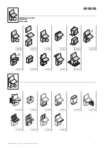
Страница 3: ...3 TopPult System TopConsole system Pupitres TopPult Inhaltsverzeichnis Contents Sommaire 500 400 4 16 37 41 17 18 18 19 20 22 23 24 25 34 35 36 21 26 27 28 29 30 30 31 32 33...

Страница 4: ...accompanying note are part of the product They must be given to the plant operator who is then responsible for the storage of the documents so that they are readily available when needed 1 3 Symbols...

Страница 5: ...d quation par Rittal Les limites de charges indiqu es dans la notice de montage doivent tre respect es Lors du d veloppement du produit d crit dans cette notice les points critiques pour la s curit on...

Страница 6: ...ienj nnite kytkent laiteyhdistelmille jossa suurin mittausj nnite on enint n 1000 V AC tai 1500 V DC ja joiden sis ll on mittaus ohjaus ja s t tekniikkaa Erityisi vaatimuksia varten ja asennettaessa u...

Страница 7: ...AC 1500 V DC Rittal DIN EN ISO 12100 Rittal 1000 AC 1500 DC Rittal DIN EN ISO 12100 Rittal 1000 V AC 1500 V DC Rittal DIN EN ISO 12100 Domeniul de utilizare Aceste produse Rittal sunt tablouri electr...

Страница 8: ...us sprendimus ir produkto rengim lauke b tina konsultuotis su Rittal atstovu Laikytis nurodyt apkrovos rib kurios apibr tos naudojimo instrukcijoje Kuriant instrukcijose apra yt produkt jau projektavi...

Страница 9: ...ada s hlas od firmy Rittal Musia by dodr an z a ov hodnoty z mont neho n vodu Pri v voji tohto produktu boli u v kon truk nom t diu vyhodnoten kritick body z h adiska bezpe nosti na z klade pos denia...

Страница 10: ...iska delar Prestare attenzione alle parti meccani che in movimento Atenci n componentes mec nicos en movimiento Die Anleitung ist zu lesen The instructions must be read La notice doit tre lue Lees de...

Страница 11: ...edningen skal l ses Przeczyta instrukcj Odkaz na instrukce n vodu k pou it bro ury P lle astuminen on kielletty Det er forbudt at klatre p maskinens overflader Zakaz wchodzenia na powierzchni Ne lapat...

Страница 12: ...hendit Izlasiet instrukciju Preberite navodila Urcarea pe o suprafa este interzis Zabranjeno je penjanje na povr inu A fel letre l pni tilos Draud iama lipti ant pavir iaus Pinna peale astumine on kee...

Страница 13: ...ti Cuidado com as partes mec nicas m veis Pre tajte si n vod Ler as instru es Je zak zan vystupova na plo inu proibido subir para a superf cie In tal ciu smie vykon va len pecializovan elektrotechnik...

Страница 14: ...ents for indoor industrial applications Pedestal 1 enclosure with door s double bit lock insert 1 mounting plate 1 accessories bag content see 3 2 1 safety instructions Desk unit 1 enclosure with lid...

Страница 15: ...706 600 TP 6707 600 TP 6710 500 TP 6711 500 TP 6714 500 TP 6715 500 TP 6720 500 TP 6721 500 TP 6712 500 TP 6713 500 TP 6716 500 TP 6717 500 TP 6722 500 TP 6723 500 Seite Page Page 1 x 1 x 1 x 21 7 2 4...

Страница 16: ...onditions apply special agreements must be made between Rittal and the user Assembly instructions Observe the load capacities specified on page 39 When installing the enclosures the mounting surfaces...

Страница 17: ...u Pultelemente 4 2 Assembly of console components 4 2 Assemblage des l ments du pupitre 1 2 1 4 2 1 2 3 3 3 1 1 1 3 1 4 2 2 3 2 3 1 2 2 1 3 1 3 4 Montage und Aufstellung 4 Assembly and siting 4 Montag...

Страница 18: ...3 Sealing plugs 4 3 Obturateurs 4 4 Montage Deckel 4 4 Mounting the lid 4 4 Montage du couvercle 4 Montage und Aufstellung 4 Assembly and siting 4 Montage et implantation 4 Montage und Aufstellung 4...

Страница 19: ...ult 1 2 3 1 4 5 2 1 1 2 3 2 5 1 4 5 T ranschlagwechsel 4 5 Switching the door hinges 4 5 Inversion du sens d ouverture 4 Montage und Aufstellung 4 Assembly and siting 4 Montage et implantation 500 400...

Страница 20: ...hsel 4 5 Switching the door hinges 4 5 Inversion du sens d ouverture 4 Montage und Aufstellung 4 Assembly and siting 4 Montage et implantation 500 400 500 400 6 6 1 6 3 6 5 6 2 6 4 6 6 MA 2 5 Nm MA 2...

Страница 21: ...ositif de verrouillage 1 2 1 1 1 3 2 1 1 5 2 3 1 2 1 4 2 2 MA 3 Nm MA 3 Nm 2435 100 2435 400 SZ 2576 000 SZ 2533 000 M5 x 6 M5 x 6 4 Montage und Aufstellung 4 Assembly and siting 4 Montage et implanta...

Страница 22: ...Montage und Aufstellung 4 Assembly and siting 4 Montage et implantation 1 3 1 3 1 3 2 2 1 3 1 2 2 2 1 2 3 3 Achtung Quetschgefahr Montage und Betrieb nur gem Anleitung Caution Danger of crushing Only...

Страница 23: ...2 4 8 Bedienung Deckel 4 8 Operating the lid 4 8 Utilisation du couvercle 1 Achtung Quetschgefahr Montage und Betrieb nur gem Anleitung Caution Danger of crushing Only to be assembled and operated in...

Страница 24: ...de montage 4 Montage und Aufstellung 4 Assembly and siting 4 Montage et implantation 1 3 5 2 4 2 4 1 3 5 1 1 2 3 4 3 2 3 3 3 6 3 6 3 6 5 1 4 2 4 3 1 2 3 1 3 5 4 1 5 2 Alternative TS 4163 000 SZ 2504 8...

Страница 25: ...usbau und Einbau Montageplatte 4 9 Removing and installing the mounting plate 4 9 D montage et montage de la plaque de montage 4 Montage und Aufstellung 4 Assembly and siting 4 Montage et implantation...

Страница 26: ...n de la plaque de montage en cas de charges dynamiques 4 Montage und Aufstellung 4 Assembly and siting 4 Montage et implantation 1 3 4 1 3 4 1 2 4 1 2 4 1 1 2 1 2 3 4 SW13 SW10 M8 x 16 M8 x 16 M8 M8 M...

Страница 27: ...e system Pupitres TopPult 4 11 Montage Sockel 4 11 Mounting the base plinth 4 11 Montage du socle 4 Montage und Aufstellung 4 Assembly and siting 4 Montage et implantation 1 1 1 1 1 1 1 2 M12 x 25 M12...

Страница 28: ...odenbleche 4 12 Installing the gland plates 4 12 Installation des plaques passe c bles 4 Montage und Aufstellung 4 Assembly and siting 4 Montage et implantation 4 Montage und Aufstellung 4 Assembly an...

Страница 29: ...trim panel 4 13 Montage de la plaque d obturation 4 Montage und Aufstellung 4 Assembly and siting 4 Montage et implantation 1 2 2 2 2 2 2 2 2 1 1 1 1 1 2 1 1 3 2 3 1 2 2 2 SW13 1 5 600 225 225 25 150...

Страница 30: ...ontage des rails pour l am nagement int rieur 4 Montage und Aufstellung 4 Assembly and siting 4 Montage et implantation 4 Montage und Aufstellung 4 Assembly and siting 4 Montage et implantation 1 1 2...

Страница 31: ...age des rails pour l am nagement int rieur 4 Montage und Aufstellung 4 Assembly and siting 4 Montage et implantation 3 3 3 2 2 1 1 1 2 3 M6 M6 M6 M6 5 5 x 13 MA 5 Nm MA 5 Nm MA 4 Nm TX25 400 500 A 500...

Страница 32: ...0 330 1 x TP 6730 340 700 N 4 16 Einbau Montageplatte in Pultmittel und Oberteil 4 16 Installing the mounting plate in the desk unit and console 4 16 Installation de la plaque de montage dans la parti...

Страница 33: ...ge de la baguette de finition en aluminium TP 4 Montage und Aufstellung 4 Assembly and siting 4 Montage et implantation 1 1 1 1 1 2 B W L 600 800 mm B W L 1000 1200 1600 mm 5 5 1 2 1 3 1 5 1 7 1 9 1 6...

Страница 34: ...sembly and siting 4 Montage et implantation 1 1 5 5 2 2 3 3 3 4 4 1 3 2 MA 8 10 Nm T D P 400 500 MA 4 6 Nm Ith 2 x TK 8 1 x 10⁶ A2S MA 10 12 Nm SZ 2564 000 SZ 2569 000 SW10 SW13 M8 M8 M8 M8 x 30 M6 x...

Страница 35: ...m TopConsole system Pupitres TopPult 4 19 Ausrichtung des Geh uses 4 19 Alignment of the enclosure 4 19 Alignement du pupitre 4 Montage und Aufstellung 4 Assembly and siting 4 Montage et implantation...

Страница 36: ...osure must be secured against tipping over during transportation assembly and installation When using a base plinth system during transportation including raising and lowering ensure that the load is...

Страница 37: ...tial equalisation between door lid and enclosure The doors lids are prepared with holes for earthing screws nuts to permit system specific earth connection All connections must be assembled in accorda...

Страница 38: ...event damage due to gaskets freezing because of low tempera tures All components and surfaces are examined for external damage Steel enclosures are also inspected for traces of corrosion Any damage is...

Страница 39: ...Largeur mm H he mm Height mm Hauteur mm Tiefe mm Depth mm Profondeur mm TP 6700 600 600 675 400 TP 6701 600 800 675 400 TP 6702 600 1200 675 400 TP 6703 600 1600 675 400 TP 6704 600 600 675 500 TP 670...

Страница 40: ...50 N 1 x 250 N 1 x 1200 N a IP nach IEC 60 529 nur in Verbindung mit montierten Seitenw nden b IK nach IEC 62 262 c Type nach UL 50 e a IP to IEC 60 529 only in conjunction with fitted side panels b I...

Страница 41: ...43078 Phone 1 800 477 4000 option 3 E mail service rittal us www rittal corp com Service HUB Indien Service HUB India Plateforme de service en Inde RITTAL India Pvt Ltd Nos 23 24 KIADB Industrial Area...

Страница 42: ...42 TopPult System TopConsole system Pupitres TopPult Notizen Notes...

Страница 43: ...43 TopPult System TopConsole system Pupitres TopPult Notizen Notes...

Страница 44: ...ftware Services www rittal com contact You can find the contact details of all Rittal companies throughout the world here RITTAL GmbH Co KG Auf dem Stuetzelberg 35745 Herborn Germany Phone 49 2772 505...

Отзывы: