


12
Rittal CMC III Access Control
6 Operation
EN
6
Operation
6.1 Activating the Access Control
After connecting the Access Control to a neighbouring
component using a CAN bus connecting cable, the
Access Control starts automatically (see section 5.4
"Connection of the Access Control"). Separate activa-
tion is not required.
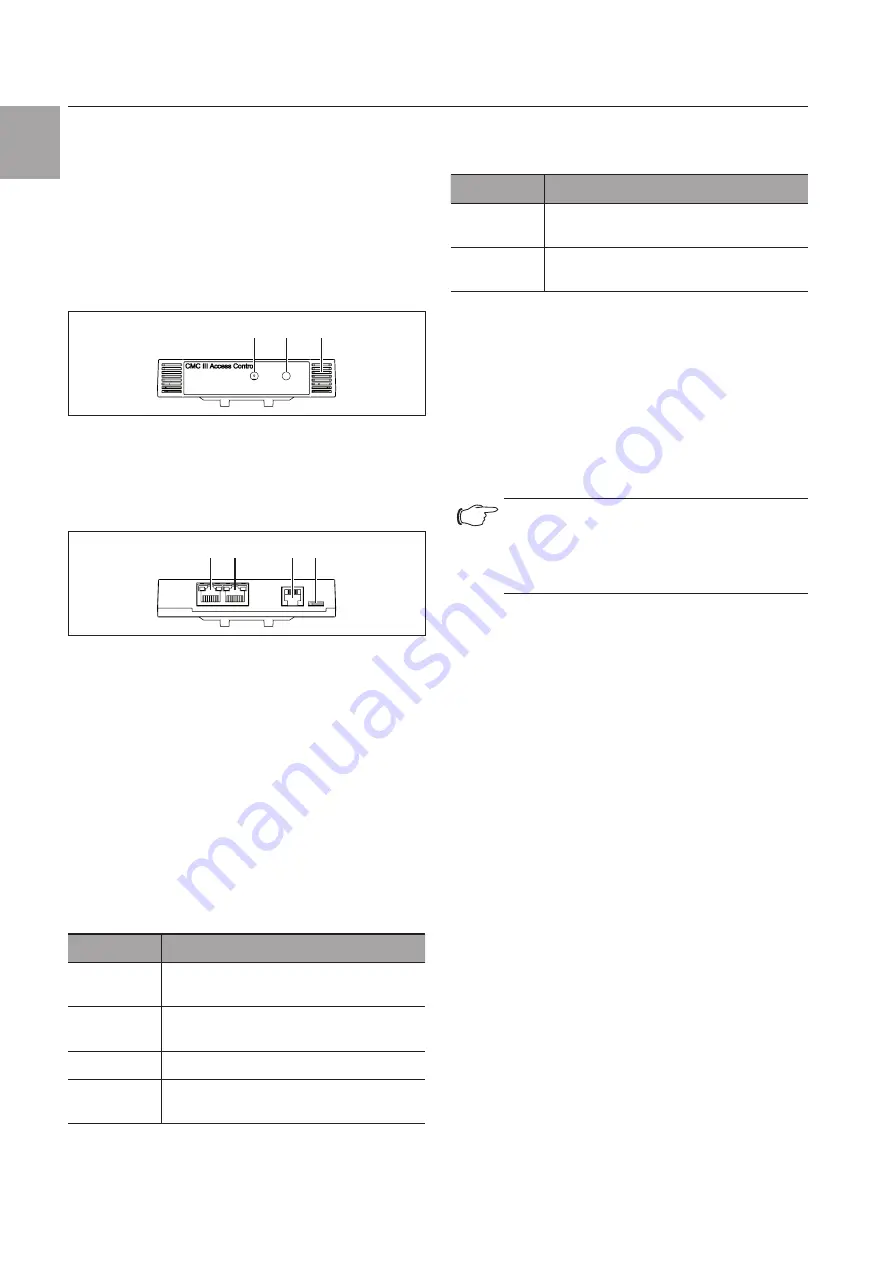
6.2 Operating and display elements
3
1
2
Fig. 12: Front of the Access Control
Legend
1
Infrared receiver
2
Infrared diode (transmitter)
3
Multi-LED for status display
4
5
6 7
Fig. 13: Rear of the Access Control
Legend
4
CAN bus connection, 24 V
5
CAN bus connection, 24 V
6
Connection for RJ 12 handle
7
Connection for CMC III reader unit
6.3 LED displays
A multi-LED for the status display is integrated into the
front of the Access Control (Fig. 12, item 3). Further
LEDs are located at the rear on the CAN bus connec-
tion (Fig. 13, item 4 and item 5).
6.3.1 Multi-LED displays
The status of the Access Control can be read on the
multi-LED.
Colour
Status
Green
When the measured value changes or, at
the latest, every 5 seconds.
Purple
A Access Control software update is
being carried out
Blue
Communication via the CAN bus.
Red
The Access Control has the "alarm"
status.
Tab. 2:
Multi-LED flashing codes
6.3.2 LED displays on the CAN bus connection
A red and a green LED are located on the CAN bus
connection. They display the status of the CAN bus.
Colour
Status
Green (con-
tinuously lit)
Communication via the CAN bus possible.
Red (flash-
ing)
Transmission fault.
Tab. 3:
LEDs for the CAN bus connection
6.4 Operating the CMC III Processing Unit
from the website
After logging on to the CMC III Processing Unit, the
web interface for operating the device is displayed.
◾ First select the "CMCIII-GRF2" entry in the navigation
area.
6.5 Configuration tab
Note:
If the access authorisations are managed
via RiZone as of version 3.6, changes must
be implemented in RiZone. In this case, no
changes may be made on the CMC III.
Similar to the CMC III Processing Unit, the
Configu-
ration
tab can be used to individually configure the
access rights for the Access Control (
Device Rights
button) and the alarm messages (
Alarm Configura-
tion
button).
6.5.1 Specification of the access authorisations
The access authorisations for the door to be monitored
are also defined in the
Configuration
tab (
Access
Configuration
button).
◾ First select the "Processing Unit" node in the naviga-
tion area.
◾ Select the
Configuration
tab in the configuration
area.
To add a new transponder card:
◾ Hold the transponder card in front of the transponder
reader
before
selecting the "Access Configurations"
dialogue.
Regardless of the next work steps:
◾ In the
Security
group frame, click on the
Access
Configuration
button.
The "Access Configurations" dialogue opens.
To add a new access code:
◾ Below the list of access codes / transponder cards
that have already been added in the
Access
group
frame of the "Access Configuration" dialogue, click
the
Add
button.


