background image

Technical specifications 

1

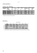
 Ambient, no heat - UF600 (IP54)

*) Depends on the design of the floor channel.

Type for indoor 
installation

Type for 
outdoor 
installation

Output 
 
[kW]

Air 
velocity* 
 
[m/s]

Voltage 
 
[V]

Amperage 
 
[A]

Dimensions  
floor channel 
[mm]

Diameter  
fans  
[mm]

Diameter 
silencer 
[mm]

UF601 Indoor UF601 Outdoor

2x4

30

400V3~

2x7,1

600x600

500

750

UF602 Indoor UF602 Outdoor

2x7,5

35

400V3~

2x13,7

750x750

630

900

UF603 Indoor UF603 Outdoor

2x11

38

400V3~

2x22

750x750

630

900

UF604 Indoor UF604 Outdoor

2x15

38

400V3~

2x28,5

750x750

630

900

UF605 Indoor UF605 Outdoor

2x18,5

40

400V3~

2x33,7

750x750

630

900

Dimensioning

Door width [m]

Door height [m] 

Other door sizes on request. For larger openings, two pillars are required. Please contact Frico. 

3 m

4 m

5 m

6 m

7 m

8 m

10 m

3 m

UF601

UF601

UF601

UF601

4 m

UF602

UF602

UF602

5 m

UF603

UF603

UF604

UF605

6 m

UF604

UF605

UF605

UF600

12

Содержание UF600 Series

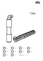
Страница 1: ...Original instructions UF600 19 DE 13 GB 16 SE 23 ES 35 NL 27 FR 31 IT 43 PL 39 NO 47 RU Appendix A 51 ...

Страница 2: ...r verwendetenTexte in englischer Sprache siehe die entsprechenden Sprachseiten DE Las páginas introductorias contienen básicamente imágenes Consulte la traducción de los textos en inglés que las acompañan en las páginas del idioma correspondiente ES De inleidende pagina s bevatten hoofdzakelijk afbeeldingen Voor een vertaling van de gebruikte Engelse teksten zie de pagina s van de resp taal NL Le ...

Страница 3: ...Outdoor installation Indoor installation 1 Intake with bird protection grille or inlet nozzle for indoor installation 2 Inlet side silencer L 1 480 mm 3 Axial fan 400V 4 Axial fan 400V 5 Motor silencer 6 Silencer pressure side L 1 000 mm 7 Floor channel Outdoor installation Indoor installation UF600 3 ...

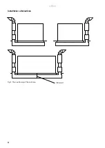
Страница 4: ...Steel wall Fig 2 The positioning of the columns Installation alternatives UF600 4 ...

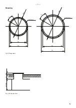
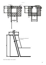
Страница 5: ...Fig 3 Flange sizes Fig 4 Connection box Ø 5 6 0 500 590 12xØ12mm 30 Ø 6 9 0 630 720 12xØ12mm 30 600 750 250 150 UF600 5 Mounting ...

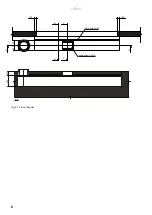
Страница 6: ...Fig 5 1 Floor channel A A 600 250 Inspection hatch 600 750 A A C C B B 150 150 Inspection hatch Air outlet slot UF600 6 ...

Страница 7: ...ig 5 2 Floor channel cross sections Slot width is determined by Frico 50 50 15 250 C C 600 750 650 800 600 750 Inspection hatch 250 25 600 750 650 800 B B 600 750 250 Air outlet slot Concrete 25 UF600 7 ...

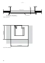
Страница 8: ...Fig 6 Air outlet slot min 150 min 150 x 250 500 Door opening If x 300 500 side protection If x 250 300 no side protection Air outlet slot Fig 7 Pit for embedment 1100 1250 1100 1250 UF600 8 ...

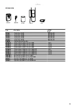
Страница 9: ...H510 Pillar extension Ø500 mm for UF601 L 1000 UFEH515 Pillar extension Ø500 mm for UF601 L 1500 UFEH520 Pillar extension Ø500 mm for UF601 L 2000 UFEH605 Pillar extension Ø630 mm for UF602 605 L 500 UFEH610 Pillar extension Ø630 mm for UF602 605 L 1000 UFEH615 Pillar extension Ø630 mm for UF602 605 L 1500 UFEH620 Pillar extension Ø630 mm for UF602 605 L 2000 UFMS750 Motor silencer Ø750 mm for UF6...

Страница 10: ...UF600 M UF600 Y 400V W2 U2 V2 U1 V1 W1 connection TK TK W2 U2 V2 U1 V1 W1 Y connection TK TK L1 L2 L3 PE TK TK L1 L2 L3 PE M Y 400V W2 U2 V2 U1 V1 W1 connection TK TK W2 U2 V2 U1 V1 W1 Y connection TK TK L1 L2 L3 PE TK TK L1 L2 L3 PE UF600 10 ...

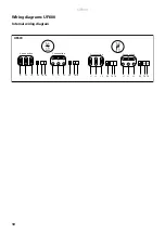
Страница 11: ...lt On Fault On Fan 1 Fan 2 Main switch Door contact 230V External on off 230V UFC600 UF600 AGB304 Alarm Indication Common Pot free contact max 5 A W1 V1 U1 V2 W2 U2 PE 3 TK TK W1 V1 U1 V2 W2 U2 PE 3 TK TK L1 L2 L3 N PE 400V3 UF600 11 ...

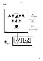
Страница 12: ...50 UF602 Indoor UF602 Outdoor 2x7 5 35 400V3 2x13 7 750x750 630 900 UF603 Indoor UF603 Outdoor 2x11 38 400V3 2x22 750x750 630 900 UF604 Indoor UF604 Outdoor 2x15 38 400V3 2x28 5 750x750 630 900 UF605 Indoor UF605 Outdoor 2x18 5 40 400V3 2x33 7 750x750 630 900 Dimensioning Door width m Door height m Other door sizes on request For larger openings two pillars are required Please contact Frico 3 m 4 ...

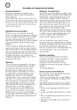
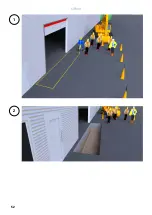
Страница 13: ...n the building considerably reduces the efficiency of the air curtain The ventilation should therefore be balanced Mounting see Appendix A The UF600 unit is assembled according to this manual and bolted together with supplied bolt kit The floor channel design choosen is cast into the floor complete with air outlet slot inspection hatch and connection box The air outlet slot should extend approxima...

Страница 14: ... risk of large amounts of water running into the floor channel a drainage pipe should be connected to the existing 1 connection internal thread Do not connect the drainage to the sewage risk of blowing out water lock Safety Do not cover surfaces of the air curtain or obstruct air inlet as this can cause excessive temperatures that can be hazardous and may cause fan motor malfunction Do not block t...

Страница 15: ...ntact Frico for more information Fig 5 5 1 Floor channel cross sections The floor channel box is a steel construction that is cast into the concrete floor The outlet opening is at floor level as close to the floor opening as possible The length of the box and the angle and column width is determined at the project planning stage The channel can be made in one piece or delivered in sections which a...

Страница 16: ...51 Appendix A UF600 ...

Страница 17: ...UF600 52 1 2 ...

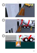
Страница 18: ...UF600 53 3 4 5 ...

Страница 19: ...UF600 54 6 7 8 ...

Страница 20: ...UF600 55 9 10 11 ...

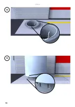
Страница 21: ...UF600 56 12 13 ...

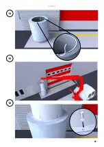
Страница 22: ...UF600 57 14 15 16 ...

Страница 23: ...UF600 58 17 18 19 ...

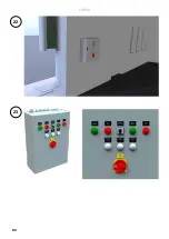
Страница 24: ...UF600 59 20 21 ...

Страница 25: ...UF600 60 22 23 ...

Страница 26: ...UF600 61 24 ...

Страница 27: ......

Страница 28: ......

Страница 29: ...0170914 HH LE Main office Frico AB Tel 46 31 336 86 00 Box 102 SE 433 22 Partille mailbox frico se Sweden www frico se For latest updated information and information about your local contact www frico se ...

Отзывы: