


Chapter 2 Port Integration Module (S12XEP100PIMV1)
MC9S12XE-Family Reference Manual , Rev. 1.19
Freescale Semiconductor
185
2.4.4
Pin interrupts
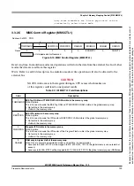
Ports P, H and J offer pin interrupt capability. The interrupt enable as well as the sensitivity to rising or
falling edges can be individually configured on per-pin basis. All bits/pins in a port share the same interrupt
vector. Interrupts can be used with the pins configured as inputs or outputs.
An interrupt is generated when a bit in the port interrupt flag register and its corresponding port interrupt
enable bit are both set. The pin interrupt feature is also capable to wake up the CPU when it is in STOP or
WAIT mode.
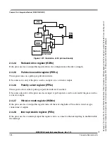
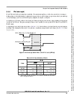
A digital filter on each pin prevents pulses (
) shorter than a specified time from generating an
interrupt. The minimum time varies over process conditions, temperature and voltage (
and
).
Figure 2-108. Interrupt Glitch Filter on Port P, H and J (PPS=0)
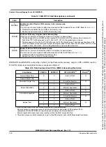
Table 2-104. Pulse Detection Criteria
Pulse
Mode
STOP
STOP
(1)
1. These values include the spread of the oscillator frequency over temper-
ature, voltage and process.
Unit
Ignored
t
pulse
≤
3
bus clocks
t
pulse
≤
t
pign
Uncertain
3 < t
pulse
< 4
bus clocks
t
pign
< t
pulse
< t
pval
Valid
t
pulse
≥
4
bus clocks
t
pulse
≥
t
pval
Glitch, filtered out, no interrupt flag set
Valid pulse, interrupt flag set
t
pign
t
pval
uncertain
Because
of
an
order
from
the
United
States
International
Trade
Commission,
BGA-packaged
product
lines
and
part
numbers
indicated
here
currently
are
not
available
from
Freescale
for
import
or
sale
in
the
United
States
prior
to
September
2010:
S12XE
products
in
208
MAPBGA
packages


