


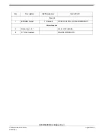

Table 2-3. LED Control
Controlled by
User LED
Color
Signal
LED1
RED
GPIO Port A, Bit 0
LED2
YELLOW
GPIO Port A, Bit 1
LED3
GREEN
GPIO Port A, Bit 2
LED4
RED
GPIO Port A, Bit 3
LED5
YELLOW
GPIO Port A, Bit 4
LED6
GREEN
GPIO Port A, Bit 5
56F8037EVM User Manual, Rev. 0
2-4
Freescale Semiconductor
Preliminary
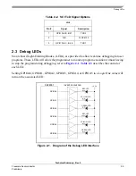
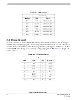
2.4 Debug Support
A JTAG connector, J1, on the 56F8037EVM allows the connection of an external Host Target
Interface for downloading programs and working with the 56F8037’s registers. This connector is
used to communicate with an external Host Target Interface, which passes information and data
back and forth with a host processor running a debugger program.
Table 2-4
shows the pin-out
for this connector.
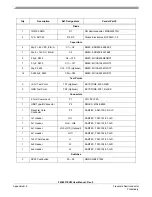
Table 2-4. JTAG Connector
J1
Pin #
Signal
Pin #
Description
1
TDI
2
GND
3
TDO
4
GND
5
TCK
6
GND
7
N/C
8
KEY
9
RESET
10
TMS
11
+3.3V DC
12
N/C
13
N/C
14
N/C
Содержание 56F8037
Страница 2: ......
Страница 4: ...56F8037EVM User Manual Rev 0 ii Freescale Semiconductor Preliminary ...
Страница 6: ...56F8037EVM User Manual Rev 0 iv Freescale Semiconductor Preliminary ...
Страница 8: ...56F8037EVM User Manual Rev 0 vi Freescale Semiconductor Preliminary ...
Страница 18: ...56F8037EVM User Manual Rev 0 1 6 Freescale Semiconductor Preliminary ...
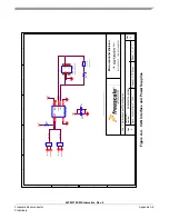
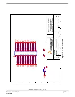
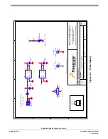
Страница 27: ...56F8037EVM Schematics Rev 0 Freescale Semiconductor Appendix A 1 Preliminary Appendix A 56F8037EVM Schematics ...
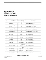
Страница 38: ...56F8037EVM User Manual Rev 0 Appendix B 4 Freescale Semiconductor Preliminary ...