background image

www.freemotionfitness.com

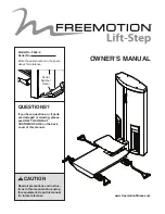
Model No. F504.0
Serial No.                                  

Write the serial number in the space 
above for reference.

    CAUTION

Read all precautions and instruc-
tions in this manual before using 
this equipment. Keep this manual 
for future reference.

QUESTIONS?

If you have questions, or if parts 
are damaged or missing, please 
see HOW TO CONTACT 
CUSTOMER CARE on the back 
cover of this manual. 

OWNER’’S MANUAL

Serial 

Number 

Decal

Содержание Lift-Step

Страница 1: ...nce CAUTION Read all precautions and instruc tions in this manual before using this equipment Keep this manual for future reference QUESTIONS If you have questions or if parts are damaged or missing please see HOW TO CONTACT CUSTOMER CARE on the back cover of this manual OWNER S MANUAL Serial Number Decal ...

Страница 2: ...RTANT PRECAUTIONS 3 WARNING DECAL PLACEMENT 4 BEFORE YOU BEGIN 5 ASSEMBLY 6 ADJUSTMENT 14 MAINTENANCE AND TROUBLESHOOTING 16 CABLE DIAGRAM 20 PART LIST 21 EXPLODED DRAWING 22 HOW TO CONTACT CUSTOMER CARE Back Cover LIMITED WARRANTY Back Cover TABLE OF CONTENTS ...

Страница 3: ...er the floor beneath the strength equipment to protect the floor 6 It is the responsibility of the owner to ensure that there is enough space around the strength equipment for the intended exercise 7 Using the anchor holes see page 5 anchor the strength equipment to the floor to pro vide maximum stability 8 Keep children under age 12 and pets away from the strength equipment at all times 9 Always ...

Страница 4: ...E WARNING Decal 3 Decal 1 Decal 2 This drawing shows the location s of the warning decal s If a decal is missing or illegible see the back cover of this manual and request a free replacement decal Apply the decal in the location shown Note The decal s may not be shown at actual size Decal 2 ...

Страница 5: ...sing the strength equipment If you have questions after reading this manual please see the back cover of this manual To help us assist you note the product model number and serial number before contacting us The model number and the location of the serial num ber decal are shown on the front cover of this manual Before reading further please review the drawing below and familiarize yourself with t...

Страница 6: ... size assemble the strength equipment in the location where it will be used Make sure that there is enough clearance around the strength equipment Place all parts in a cleared area and remove the packing materials Do not dispose of the packing materials until assembly is completed Assembly requires a set of metric hex keys To avoid damaging parts do not use power tools 73 73 73 68 68 68 1 2 1 ...

Страница 7: ...and the Access Cover 41 from the Tower 1 74 59 41 1 3 59 74 59 74 74 59 59 74 59 74 2 Tip It may be helpful to adjust the height of the Platform 3 to do this step see ADJUSTING THE PLATFORM on page 14 Insert the free end of the Resistance Cylinder 18 into the tab underneath the Platform 3 Then tighten an M8 Locknut 77 with an M8 Washer 71 onto the Resistance Cylinder 3 71 Tab 2 77 18 ...

Страница 8: ... M10 x 20mm Screws 62 the four M10 Washers 72 and the Tower Brace 8 5 Remove the four M6 x 16mm Screws 57 and the four M6 Washers 70 from the Cap 38 Then remove the Cap 38 and set it aside 5 4 62 8 72 72 57 70 70 38 57 70 ...

Страница 9: ...es 34 on one side of the Tower 1 Note After you remove these parts the Weight Guides 34 will slide downward a few inches into the Tower 1 7 Pull the upper ends of the two Weight Guides 34 toward you Remove the remaining Plastic Washers 36 Weight Guide Spacers 35 M16 Split Washers 81 and M16 Jam Nuts 80 from the Weight Guides 7 6 81 81 35 35 80 36 36 1 81 35 80 36 34 34 ...

Страница 10: ...9 and find the decal that has the largest number on it Orient that Weight as shown at the right and slide it onto the Weight Guides 34 Repeat this step with the remaining 16 Weights 29 in the stack Then look at the decals on all the Weights and make sure that the Weights are in the correct order 9 Slide the Weight Carriage 26 onto the Weight Guides 34 and rest the Weight Carriage on the stack of W...

Страница 11: ... oriented as shown in the inset drawing 11 Note This step requires the parts that you removed in step 6 Lift the Weight Guides 34 a few inches Slide the two Plastic Washers 36 the two Weight Guide Spacers 35 and the two M16 Split Washers 81 onto the Weight Guides Make sure that the Weight Guide Spacers are oriented as shown in the inset drawing In addition make sure that the Weight Guide Spacers a...

Страница 12: ...he strength equipment 13 Note This step requires the parts that you removed in step 5 Attach the Cap 38 to the Tower 1 with the four M6 x 16mm Screws 57 and the four M6 Washers 70 start all the Screws and then tighten them 13 12 1 57 70 70 38 57 70 ...

Страница 13: ...ep 3 Attach the Access Cover 41 to the Tower 1 with the six M6 x 10mm Screws 59 and the six M6 Large Washers 74 start all the Screws and then tighten them 15 14 Note This step requires the parts that you removed in step 4 Attach the Tower Brace 8 to the Tower 1 with the four M10 x 20mm Screws 62 and the four M10 Washers 72 start all the Screws and then tighten them 62 8 1 72 72 74 59 41 1 59 74 59...

Страница 14: ...ake sure that all parts are properly tightened each time the strength equipment is used Replace any worn parts immediately ADJUSTMENT Weight ADJUSTING THE PLATFORM To adjust the height of the platform pull the latch handle move the platform upward or downward to the desired position and then release the latch handle Then move the platform upward or down ward slightly until it locks into position L...

Страница 15: ...ING THE LONG HANDLES The long handles can be attached to the cable clips in any of three positions To attach a long handle insert the desired ring on the long handle into a cable clip Cable Clip Long Handle Ring ...

Страница 16: ...s or damage resulting from the use or misuse of cleaning products IMPORTANT When using any cleaning product try it first in a hidden place to ensure that there is no damage to the material Do not use abrasive cleaners strong cleaners or solvents such as lacquer thinner kerosene gasoline or similar liquids Such substances may scratch the strength equipment damage plastic parts and decals or cause o...

Страница 17: ... cables must be tensioned correctly To check the tension of each cable slowly raise and lower the appli cable weight carriage by performing one repetition If there is not enough tension on a cable the weight carriage will not be lifted immediately when the repeti tion is begun Ideally the cable should not move more than 1 2 in 1 3 cm from the resting position before the weight carriage is lifted I...

Страница 18: ...d of the cable 6 Reinsert the cable and the sheath into the cable clip so that all of the bare cable is in the hole 7 Retighten the four set screws equally until they contact the cable Then tighten each set screw alternately 1 4 turn until all are set to 85 inch pounds 9 6 Newton meters 8 Slide the cable stop onto the cable clip remove the weight pin and lower the handle 9 Check for proper tension...

Страница 19: ...th equipment for increased clearance 4 Using a punch drive the four old bushings out of the weight carriage 5 Hold one of the new bushings square with the face of one of the holes in the weight carriage place a piece of scrap wood on top of the bushing and tap the bushing into place until the bushing is flush with the hole in the weight carriage Insert the other three new bushings in the same way ...

Страница 20: ...ach cable Use the diagram to make sure that the cables and the cable traps are assembled correctly If a cable is not cor rectly routed the strength equipment will not function properly and damage may occur Make sure that the cable traps do not touch or bind the cables 7 2 5 6 9 8 1 3 10 11 4 7 2 5 6 9 8 1 10 11 4 ...

Страница 21: ...er 37 4 Weight Bumper 38 1 Cap 39 1 Cap Trim 40 4 Cap Post 41 1 Access Cover 42 4 Pulley Cover A 43 4 Pulley Cover B 44 4 Pulley Cover Bushing 45 2 Weight Carriage Bumper 46 2 Cable Clip 47 4 Cable Stop 48 1 Spring 49 20 Flange Bushing 50 2 Latch Spacer 51 8 Pulley Bearing 52 4 Snap Ring 53 4 Roll Pin 54 13 8 x 13mm Screw 55 14 6 x 10mm Screw 56 8 M5 x 16mm Screw 57 8 M6 x 16mm Screw 58 2 M8 x 25m...

Страница 22: ... 52 51 44 53 69 47 47 66 68 68 72 73 71 71 77 77 73 72 72 11 82 21 83 18 5 6 49 49 49 49 75 75 75 75 61 61 61 61 61 4 20 2 42 43 3 9 9 10 63 72 63 63 79 56 63 72 32 60 61 21 83 EXPLODED DRAWING A Model No F504 0 R1213B ...

Страница 23: ... 20 29 65 54 72 78 27 27 27 72 32 60 72 72 8 62 31 55 55 55 33 60 40 40 38 57 70 57 70 39 24 57 57 54 54 54 54 70 70 57 70 20 65 72 88 25 20 20 20 65 72 72 72 67 72 78 78 32 23 85 87 86 22 13 12 60 1 70 76 16 70 50 50 76 48 71 58 17 7 84 84 71 58 45 EXPLODED DRAWING B Model No F504 0 R1213B ...

Страница 24: ...proper service 4 Users in excess of the maximum user weight listed in this manual 5 Damage caused by moving the product or improper stor age including moving or storing the product on its side 6 Use or storage of the product outdoors or in high humidity environments including spa and pool areas 7 Damage caused by improper wiring or insufficient electri cal current Note This product may not have wi...

Отзывы: