29
Understanding the LEDs
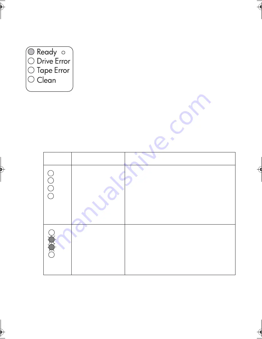
LEDs during self-test
Your Ultrium tape drive has four LEDs (light emitting diodes) on the front
panel, which indicate drive status, and two LEDs on the rear panel. The
power switch is also illuminated when power is switched on. These LEDs
provide useful troubleshooting information.
The tape drive performs a power on self-test whenever power is applied or
the drive is reset. The test takes about 5 seconds.
The green Ready light flashes several times and then remains on if self-test
passes. All other LEDs remain off.
If the self-test fails, the Drive Error and Tape Error LEDs flash, while the
Ready and Clean LEDs are off. This continues until the drive is reset.
Using the LEDs for troubleshooting
Use the following table to interpret the front panel LED sequences and the appropriate action
to take, if any.
LED
Sequence
Cause
Action required
All LEDs OFF
.
Drive may not have
power, may be faulty or
may have been power
cycled or reset during a
firmware upgrade.
Make sure the drive is switched on. The power on/
off switch incorporates a green LED.
If this is not on, check the power cable connection
and replace the cable if necessary. You can use the
power cable from your monitor or another device to
check that the connection is working.
If the power supply is present and all LEDs remain
off, press emergency reset (see page 32) or power
cycle the drive. If it still fails, call for service.
Ready and Clean OFF.
Drive Error and Tape Error
FLASHING
.
The drive has failed to
execute power-on self
test (POST).
Power cycle or reset the drive (see page 32).
If the error condition reappears, call for service.
gen2 external oem.fm Page 29 Thursday, February 13, 2003 3:02 PM
Содержание Ultrium Generation 2
Страница 1: ...8OWULXP HQHUDWLRQ WHUQDO 7DSH ULYHV HWWLQJ 6WDUWHG XLGH...
Страница 2: ......
Страница 10: ...8 Figure 2 checking the SCSI connection connecting to a FC SCSI bridge connecting to an HBA card in the server...
Страница 12: ...10 3 Figure 3 checking the SCSI ID...
Страница 14: ...12 Figure 4 connecting the SCSI cable SCSI IN Connector SCSI OUT Connector...
Страница 16: ...14 Figure 5 connecting the power cable...
Страница 22: ...20 Figure 8 write protecting cartridges padlock indicates cartridge is protected...
Страница 36: ...34...


