Francis A7290 Скачать руководство пользователя страница 47

Failure of Lamp to Ignite 
 

In the event of the xenon lamp failing to light the following steps should be taken: 
 

1) 


Check that the mains supply is connected to the input of the PSU. On operating the lamp 
switch, if the lamp does not light, switch off mains supply and check all fuses. 

2) 


On pressing the lamp switch the lamp still does not ignite, check the searchlight head. On 
your command get an operator to activate the switch for approximately 10 seconds. During 

this time listen for any noise (cracking or hissing) coming from within the barrel. If this 
arcing is heard switch off the supply at the mains. Remove the rear bezel to expose the two 
supply leads to the xenon lamp. Using a dry cloth wipe these leads to remove any dust, 
moisture or condensation that may have formed around the inside of the barrel. Replace 

the rear bezel, ensuring the latches are located, and perform the check again, listening for 
the cracking. If the lamp still fails to ignite, switch off at the mains and replace the xenon 
lamp in accordance with the safety procedures within this manual and the 

manufacturer’s


information.


Any further tests to be carried out with regards to lamp failure must be conducted by a 
competent electrical engineer and should not be carried out in an explosive atmosphere. 


3) 


Before a xenon lamp will ignite, the electrically insulated gas between the electrodes must 
be ionised. This is done by the ignitor which produces a high frequency voltage (up to 
30,000 volts or higher). The ignitor is activated by switching the lamp on and a crackling or 

hissing noise should be heard. The ignitor is housed within the rear of the searchlight 
barrel. This is a totally encapsulated unit and repair is not advised. If found to be faulty a 
new ignitor must be fitted. 


Failure of Remote Focus Facility 

 
The remote focus mechanism is controlled by a small electric motor situated at the rear of the 

searchlight barrel. If the focus of the light fails, the following procedure should be adopted: 
 
1) 


Remove the rear bezel from searchlight barrel and examine focus mechanism. If parts 
have become loose, tighten fasteners. The mechanism operates on a lever action, and this 

should be checked for correct positioning. 

2) 


If the mechanism is okay, check the supply to the motor. This can be done by simply 
placing a multi-meter across the motor terminals. 

3) 


If supply is present, this indicates that the motor has failed. Replace the focus motor 

ensuring that the assembly is correct. 

4) 


If no supply is present, there is a fault in the motor gearbox. This should be examined and 
rectified accordingly. 


Note: If a fault occurs on the motor gearbox, the unit should be returned to Francis 
Searchlights Limited for fault evaluation and repair. 


Back To Top


Содержание A7290

Страница 1: ...eference Number A7290 FX560RC 5Kw 440v 3 phase 50 60Hz Manufacturer s details Distributor details Manual Part Number C29238 Issue 1 3 8 21 Francis Searchlights Ltd Union Road Bolton Lancashire BL2 2HJ...

Страница 2: ...ty Precautions 3 Technical Information 4 Unpacking and Installation Instructions 5 Electrical Installation 6 Operating Instructions 7 Fault Finding 8 Maintenance and Servicing 9 General Assembly Wirin...

Страница 3: ...optimum performance and service life The Francis Xenon range combines features proven over many years service in the most hazardous conditions in both marine and land installations To prolong the life...

Страница 4: ...he searchlight off Never place anything on or cover the searchlight when in use Ensure the lamp has cooled sufficiently before removal If undue force appears necessary to remove the lamp the equipment...

Страница 5: ...Box Barrel Weight Searchlight 88Kgs PSU Assembly 61Kgs The searchlight also performs to the following optical data Xenon light source Lamp Wattage 5000 Watts Supply voltage 440V three phase 50 60Hz Pe...

Страница 6: ......

Страница 7: ......

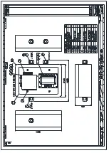
Страница 8: ...Remove front panel for AC DC wiring connections Back To Top...

Страница 9: ...INPUT 4 CORE 2 5mm TE2 50mm WELDING CABLE S50 2 CORE 1 5mm D1...

Страница 10: ......

Страница 11: ...ly before being installed Installation procedures should be adhered to to ensure a safe working environment and reduce the risk of damage or personal injury Preparing the Mounting Position Mark out an...

Страница 12: ...1 Disconnect the supply before working on the electrical system 2 The searchlight must be connected to a fused electrical supply using suitably sized cable 3 If the searchlight is located a considera...

Страница 13: ...ick Control Panel is supplied Cables required to be connected by the customer Ethernet cable from the Interface Output Enclosure to the Data Switch Fibre Optic cable from the Data Switch to the networ...

Страница 14: ...separately using the M5 grub screw J 6 The lamp can now be inserted with the lamp holder socket into the lamp holder rear I the negative cathode end of the lamp is towards the rear of the searchlight...

Страница 15: ......

Страница 16: ...le to move the beam in both directions at once by moving the joystick diagonally Home The lamp can be returned to a pre set home position By default this is dead ahead with the beam level although dif...

Страница 17: ...d Note that this may not actually be a fault The LED will flash when a limit switch is operated under normal circumstances i e the lamp is at the limit of travel This will also indicate when a variabl...

Страница 18: ...ror Some lamp types do not use all or some limit switches If an invalid limit switch input is detected it is probable the speed control card is set to the wrong product or there is a wiring error 9 Da...

Страница 19: ...as mechanical stresses MUST be avoided Ensure that the spring contacts firmly surround the pins on the cap of the lamp Do not apply unnecessary force when tightening the screws After inserting the la...

Страница 20: ...r average lamp life and not later than 1 25 times their average lamp life After this time there is an increased risk of the lamp exploding 3 The anode positive cap marked must be on top when the lamp...

Страница 21: ...ck Wire ER Pan Encoder Red Wire 5V EG Pan Encoder Green Wire Phase A Output EW Pan Encoder White Wire Phase B Output 0V Pan Encoder Black Pan Limit Switch Common CL Pan Clockwise Limit Switch Orange W...

Страница 22: ...FBUS Speed Control Board...

Страница 23: ...OV Supply Input T Line Terminate Connect to for terminate FBUS RS485 Data In Out FBUS RS485 Data In Out 24 24V Supply Input JOYSTICK CONNECTOR BK Joystick Black Wire Y Joystick Yellow Wire BL Joystic...

Страница 24: ...on For example if switches 6 and 8 are on and all others are off the address value would be 5 Note that switches 1 3 are not used for address selection and should be switched off STANDARD CONTROL PAN...

Страница 25: ...hould be set to 0 1 and 2 Control panel panel addresses use the same system being sequential and start from zero It is essential that all lamps have a unique address with no duplication It is essentia...

Страница 26: ...nels use different address ranges with panels being addresses 0 15 and lamp addresses starting at 16 and going up to 56 A lamp whose address was set to 0 on the address switches will actually be addre...

Страница 27: ...the lamp rotate slowly clockwise Increasing the value will make the lamp move faster A value of 126 will make the lamp rotate slowly anticlockwise Decreasing the value will make the lamp move faster T...

Страница 28: ...Hex 0F This is a single byte command which activates when the home button is pressed and held for 5 seconds Home Long Press This is used to store a new home position A lamp receiving this command wil...

Страница 29: ...st transmit its first data byte pan position within 1mS of receiving its standard address and the gaps between successive bytes must be less than 1mS Lamp TX Byte 1 Pan position LSB Lamp TX Byte 2 Pan...

Страница 30: ...e next six bytes which will comprise the lamps transmitted data as described above A detailed description of transmitting and receiving is described below TRANSMITTING TO A LAMP Basically any sending...

Страница 31: ...bus 3 If desired check the last of the six bytes which is the CRC 4 Read the two bytes which will be a value centred on 2048 increasing for clockwise from centre and decreasing for anticlockwise This...

Страница 32: ...essive current The motor will be disabled for a period when this occurs Fault indication will remain until power is removed or the fault is corrected 4 Tilt motor over current The tilt motor is taking...

Страница 33: ...tates control of up to 12 searchlights from a PC The system communicates to Francis Searchlights FBUS data system using one or more FBUS Interface units Communication between the PC and FBUS interface...

Страница 34: ...With this configuration the system will communicate to one FBUS interface The second mode facilitates communication with lamps in different locations using a number of FBUS interfaces with independen...

Страница 35: ...to suite the network conditions ENABLE FOCUS POSITION Some lamp types provide a value relating to the lamps Focus Setting this checkbox displays the Focus setting in the main window ENABLE STATUS BUTT...

Страница 36: ...the lamp to home the home button will turn red while the lamp is moving to home PLAY The FBUS system can store and recall sequences of lamp motion and lamp on off switching Pressing the play button w...

Страница 37: ...ther POSITION VALUES The position window displays the currently selected lamps position The values for pan and tilt are both referenced from mid centre The display values are in degrees with a resolut...

Страница 38: ...en used with Francis searchlights FBUS Control software the FBUS interface can control networks of lamps over local communication systems or globally via the internet POWER FBUS CONNECTION The FBUS in...

Страница 39: ...iven lamp The default display described above displays data from a given lamp The set lamp address item is used to define the given lamp number Note that this setting does not alter the interface oper...

Страница 40: ...any faults or limit switch activation relating to the selected lamp Multiple faults will be displayed sequentially LAMP SOFTWARE Displays the currently selected lamp software version LAMP TYPE No Dis...

Страница 41: ...sent All commands are detailed below DATA_LAMP_BUTTON 0x0A Four byte command Sync Lamp address command CRC Switches the lamp state from on to off or off to on DATA_FOCUS BUTTON 0x0B Four byte command...

Страница 42: ...peed value is between 0 and 127 Value 0 stops pan motion and cancels the command Increasing values make the lamp move progressively faster Transmitting codes Hex 0xFF 0x90 0x15 0x7F would move lamp 0...

Страница 43: ...P_ON 0x1A Four byte command Sync Lamp address command CRC The lamp will switch on when this code is received DATA_LAMP_OFF 0x1B Four byte command Sync Lamp address command CRC The lamp will switch off...

Страница 44: ...ill switch to transmit and send 13 bytes as detailed below 1 Sync FF 2 Lamp Address with bit 7 set range 0x90 0xA8 3 Pan Position LSB Same format as pan position command above 4 Pan Position MSB 5 Til...

Страница 45: ...AD2_ON command This command is included to allow systems which have a low refresh rate to control the focus motor ERROR CONTROL CRC Error control is implemented with a CRC following each data packet T...

Страница 46: ...ry Arc unsteady Lamp operated outside current control range Magnetic stabilisation for horizontal operation defective Correct current setting Check magnetic stabilisation Bulb draws in air Crack in gr...

Страница 47: ...osive atmosphere 3 Before a xenon lamp will ignite the electrically insulated gas between the electrodes must be ionised This is done by the ignitor which produces a high frequency voltage up to 30 00...

Страница 48: ...ide of the searchlight The following procedure should be adhered to Remove the front bezel Clean the front glass inside and out using a proprietary glass cleaner Clean the reflector if required Check...

Страница 49: ...Number Description A7290 FX560RC 5Kw G A N A Wiring Schematic C29237 Wiring Diagram C27312 Joystick Panel Assembly C29195 Interface Output Enclosure Assy C29203 Junction Box Assy C29078 Interface Inpu...

Страница 50: ......

Страница 51: ......

Страница 52: ......

Страница 53: ......

Страница 54: ......

Страница 55: ......

Страница 56: ......

Страница 57: ......

Страница 58: ...00 Front Rear Bezel Gasket C24706 01 Motor Remote Focus C15459 00 Bearing C27288 01 Heater C06779 00 Reflector C20281 00 Bellows Enclosure Spares C29079 00 PCB Interface Unit Input C28614 00 PCB Inte...

Страница 59: ...re parts This will ensure that any warranties on your equipment will not be invalidated When ordering spare parts please contact the Sales Department at Francis Searchlights Limited Please always quot...

Отзывы: