background image

INSTALLATION

Motor

8

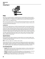
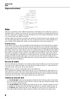
Wiring Diagram

Motor

Each motor is provided with heat sensors attached directly to the motor windings. These devices open if the 
motor windings experience excessive heat, thereby opening the circuit in the control panel, cutting off power to 
the pump. When the motor is stopped due to an overheated condition, it will restart automatically when the 
motor has cooled to an acceptable temperature. 
Pumps must be properly connected to a control panel with thermal and overload protection, and shall be rated 
or set to a maximum ampere rating. The heat sensor leads are BLACK and RED and should be connected to the 
thermal sensor terminals in the control panel.

Leak Detection

The motor has an integral moisture sensor that must be properly connected to a control panel with seal-fail cir

-

cuitry. The pump can be removed from service when moisture is detected in the seal-fail chamber. The presence 
of water in this chamber energizes the seal leak warning light inside the control panel (if so equipped with this 
option). The moisture sensor lead is WHITE, and should be connected to the seal terminal in the control panel. 
The green ground wire must be properly grounded inside the control panel for the moisture sensor to operate 
correctly. This is a Warning Light only, and will not keep the pump from continuing to operate. Allowing the unit 
to continue to operate after the warning can allow moisture to enter into the motor housing and damage the 
motor. It is vitally important to remove the pump from service and repair the lower seal assembly to prevent 
damage to the pump motor and wiring.

Impeller Rotation

Improper impeller rotation will result in damage to the pump. Rotation must be checked at installation. After 
completing the wiring and with the disconnect switch in the “off” position, lay pump on the side to observe the 
direction of rotation through the intake. 

NOTE:

 Contacting an energized pump could result in electrical shock. 

Turn disconnect switch to the “On” position momentarily. The impeller should be rotating counterclockwise. An 
alternate method to determine rotation direction is to observe the kickback of the freely suspended pump as it 
starts. The kickback should be in counterclockwise direction looking at the top of the pump. To change the direc

-

tion or rotation, interchange any two of the white, red, or black wires of the pump at the disconnect box.

Level Sensing Controls

Pump Off

 Control: Should be set to turn the pump off when the water level is at the top of the motor hous

-

ing. By setting the control at this point you are utilizing the liquid being pumped to help cool the motor 
which improves the life expectancy of the motor.

Pump On

 Control: Should be set to turn the pump on between 6" to 12" below the Lag/Alarm control device. 

An optimum cycle for these products would be between 2 to 3 minutes of run time per cycle.

Lag/Alarm

 Control: Should be set between 6" to 12" below the inlet of the station. It is important to note 

that no control device should ever be set above the inlet of any station.

Содержание 3NC

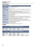
Страница 1: ...S 2 PRODUCT DESCRIPTION 3 Model Number 3 PRODUCT DESCRIPTION 4 3 Discharge Models 4 4 Discharge Models 5 Specifications 6 Flow Rates 6 INSTALLATION 7 Physical Installation 7 Electrical Connection 7 Wi...

Страница 2: ...ounding conductor To reduce risk of electric shock be certain that it is properly connected to ground To avoid hazards when installing or servicing install a double pole disconnect near the pump insta...

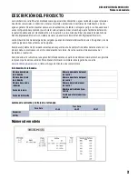
Страница 3: ...ng 2 5 spherical solids and four inch discharge flange pumps can handle 3 spherical solids Please examine your item s carefully to ensure that no damage occurred during shipment If damage has occurred...

Страница 4: ...22 5 3NC 323P3 184 16 15 200 230 3 3NC 523P1 160 19 3NC 323P3 172 14 5 13 5 3NC 523P3 196 21 18 5 200 230 3 3NC 323P3 160 13 5 12 3NC 523P3 184 16 15 3NC 346P3 184 7 5 460 3NC 523P3 172 14 5 13 5 3NC...

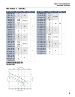
Страница 5: ...P3 190 8 5 575 4NC 357P3 170 5 5 575 4NC 7557P3 182 8 4NC 357P3 160 5 4NC 7557P3 170 7 4NC 357P3 146 4 5 4NC 7557P3 160 6 5 4NC 523P1 176 30 230 5 1 4NC 1023P3 206 26 26 200 230 10 4NC 523P1 170 24 4N...

Страница 6: ...con Carbide with nitrile NBR cup additional exclusion seal seal fail indication probe Power Cord 30 or 50 8 AWG stranded 4 conductor oil and water resistant Type SOOW or SEOOW rated for 600 V 40 C to...

Страница 7: ...ust not be modified in any way with the exception of shortening the cord to fit into a control panel Any splice between the pump and the control panel must be made within a junction box and comply wit...

Страница 8: ...nter into the motor housing and damage the motor It is vitally important to remove the pump from service and repair the lower seal assembly to prevent damage to the pump motor and wiring Impeller Rota...

Страница 9: ...dication of motor overloading overheating which can be caused by appli cation issues such as an obstructed pump impeller switch stuck in the ON position pump running dry pump air locked pump short cyc...

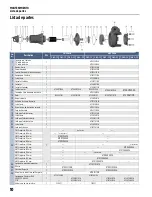
Страница 10: ...8752138102A 16 Lower Bearing Plate 1 8730532102A 17 Mechanical Seal 1 8720375102A 18 Seal Fail Sensor Kit 1 8730528101A 19 O Ring 1 8720114127A 20 Seal Fail Cover 1 8700225151A 21 Seal Fail Bolt Kit 1...

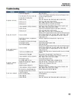
Страница 11: ...not discharge liquid Lift too high for pump Check rated pump performance table Inlet to impeller plugged Pull pump and clean Pump is air locked Shut power offfor approximately 1 minute then restart R...

Страница 12: ...800 348 2420 franklinengineered com For technical assistance parts or repair please contact Form 998779 Rev 001 07 20 Copyright 2020 Franklin Electric Co Inc All rights reserved...

Страница 13: ...RE SEGURIDAD 2 DESCRIPCI N DEL PRODUCTO 3 N mero de modelo 3 PRODUCT DESCRIPTION 4 Modelos de la serie 3NC 4 Modelos de la serie 4NC 5 Especificaciones 6 Caudales 6 INSTALACI N 7 Instalaci n f sica 7...

Страница 14: ...a tierra Para reducir el riesgo de una des carga el ctrica aseg rese de que est correctamente conectadaa tierra Para evitar riesgos instalando o atendiendo instale un doble poste desconectan cerca de...

Страница 15: ...s y las de cuatro pulgadas s lidos esf ricos de 3 pulgadas Examine su s elemento s cuidadosamente para asegurar que no haya n sufrido da os durante el env o Si se produjo da o comun quese con el sitio...

Страница 16: ...3P1 172 22 5 3NC 323P3 184 16 15 200 230 3 3NC 523P1 160 19 3NC 323P3 172 14 5 13 5 3NC 523P3 196 21 18 5 200 230 3 3NC 323P3 160 13 5 12 3NC 523P3 184 16 15 3NC 346P3 184 7 5 460 3NC 523P3 172 14 5 1...

Страница 17: ...3 146 5 5 4NC 7557P3 190 8 5 575 4NC 357P3 170 5 5 575 4NC 7557P3 182 8 4NC 357P3 160 5 4NC 7557P3 170 7 4NC 357P3 146 4 5 4NC 7557P3 160 6 5 4NC 523P1 176 30 230 5 1 4NC 1023P3 206 26 26 200 230 10 4...

Страница 18: ...s y dep sito de carburo de silicio con nitrilo NBR fijo sello de exclusi n adicional sonda de indicaci n de falla del sello Cable de alimentaci n De 30 pies o 50 pies 8 AWG trenzado de 4 conductores r...

Страница 19: ...ar el cable a fin de que se adecue al panel de control Todo empalme entre la bomba y el panel de control debe realizarse en una caja de conexiones y debe cumplir con el C digo El ctrico Nacional El co...

Страница 20: ...e la advertencia puede ingresar agua a la carcasa del motor y as da arlo Es de vital importancia quitar la bomba de funcionamiento y reparar el montaje del sellado inferior para evitar que se da e el...

Страница 21: ...amiento de protector es una indicaci n de sobrecarga sobrecalentamiento del motor que puede ser causado por problemas con la aplicaci n como un impulsor de bomba obstruido interruptor trabado en posic...

Страница 22: ...aca de cojinete 1 8730532102A 17 Sello de Mec nico 1 8720375102A 18 Sello para fallas de sensor 1 8730528101A 19 Junta t rica 1 8720114127A 20 Sello para fallas de cubierta 1 8700225151A 21 Sello para...

Страница 23: ...minuto luego react vese Repita varias veces para limpiar el aire de la bomba Si el sistema incluye una v lvula de control un 3 16 pulgada agujero deber a ser taladrado en el tubo de descarga aproxima...

Страница 24: ...800 348 2420 franklinengineered com Para la ayuda t cnica por favor p ngase en contacto Form 998779 Rev 001 07 20 Copyright 2020 Franklin Electric Co Inc Todos los derechos reservados...

Страница 25: ...des mati res CONSIGNES DE S CURIT 2 DESCRIPTION DU PRODUIT 3 N mero de modelo 3 D charge bride 3 4 D charge bride 4 5 Sp cifications 6 D bits 6 INSTALLATION 7 Installation physique 7 Raccordements lec...

Страница 26: ...lectrique assurez vous de seulement brancher la pompe une prise lectrique correctement mise la terre Pour viter tout risque de d charge lectrique lors de l installa tion ou de l entretien installez un...

Страница 27: ...de 10 16 cm 4 po peuvent traiter des l ments solides de forme sph rique de 7 62 cm 3 po Veuillez inspecter soigneusement votre ou vos articles pour v rifier qu aucun dom mage n est survenupendant le...

Страница 28: ...5 3NC 323P3 184 16 15 200 230 3 3NC 523P1 160 19 3NC 323P3 172 14 5 13 5 3NC 523P3 196 21 18 5 200 230 3 3NC 323P3 160 13 5 12 3NC 523P3 184 16 15 3NC 346P3 184 7 5 460 3NC 523P3 172 14 5 13 5 3NC 34...

Страница 29: ...4NC 7557P3 190 8 5 575 4NC 357P3 170 5 5 575 4NC 7557P3 182 8 4NC 357P3 160 5 4NC 7557P3 170 7 4NC 357P3 146 4 5 4NC 7557P3 160 6 5 4NC 523P1 176 30 230 5 1 4NC 1023P3 206 26 26 200 230 10 4NC 523P1 1...

Страница 30: ...BR et soufflet fixe en carbure de silicium avec coupelle en nitrile NBR joint d tanch it suppl mentaire sonde d indication de rupture du joint d tanch it Cordon d alimentation 4 conducteurs c bl s de...

Страница 31: ...pouvoir flexible mont la pompe ne doit pas tre modifi de toute fa on l exception de la mati re grasse de la corde pour s inscrire un panneau de contr le Chacun colle entre la pompe et le panneau de c...

Страница 32: ...peut faire p n trer l humidit dans le carter du moteur et endommager le moteur Il est extr mement important d arr ter la pompeet r parer la garnitured tanch it inf rieure d s que le voyant s allume po...

Страница 33: ...une indication de surcharge surchauffe du moteur qui peut tre caus e par des prob l mes d applications telles un turbine de pompe obstru un interrupteur bloqu en position ON pompe s che pompe obstru e...

Страница 34: ...rique 1 8752138102A 16 Abaissez le boulon de plaque de rou lement 1 8730532102A 17 M canique Joint 1 8720375102A 18 chouer de Joint Sonde Ensamble 1 8730528101A 19 Joint torique 1 8720114127A 20 choue...

Страница 35: ...air dans la pompe Couper le courant pendant 1 minute environ puis recommencer R p ter cette op ration plusieurs fois pour vacuer l air de la pompe S il y a une soupape d arr t percer un trou de 3 16...

Страница 36: ...800 348 2420 franklinengineered com Pour l aide technique entrez s il vous pla t en contact Form 998779 R v 001 07 20 Copyright 2020 Franklin Electric Co Inc Tous les droits r serv s...

Отзывы: