15
Chapter 2 Installation Instructions
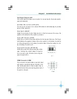
Front Audio Connector: F_AUDIO
The audio connector provides two kinds of audio
output choices: the Front Audio, the Rear Audio.
Their priority is sequenced from high to low (Front
Audio to Rear Audio). If headphones are plugged
into the front panel of the chassis (using the Front
Audio), then the Line-out (Rear Audio) on the rear
panel will not work. If you do not want to use the
Front Audio, pin 5 and 6, pin9 and 10 must be
short, and then the signal will be sent to the rear
audio port.
S/PDIF Out Connector: SPDIF_OUT (optional)
The S/PDIF out connector is capable of provid-
ing digital audio to external speakers or com-
pressed AC3 data to an external Dolby digital
decoder.
Note:The empty pin of S/PDIF cable should be
aligned to empty pin of S/PDIF out connector.
SPDIF_OUT
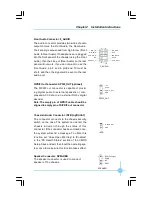
Chassis Intruder Connector: INTR
(optional)
The connector connects to the chassis security
switch on the case. The system can detect the
c hassis intru sion throu gh the statu s of this
connector. If the connector has been closed once,
the system will send a message. To utilize this
function, set
“
Case Open Warning
”
to
“
Enabled
”
in the
“
PC Health Status
”
section of the CMOS
Setup. Save and exit, then boot the operating sys-
tem once to make sure this function takes effect.
INTR
1
I NTRUDE RJ
GND
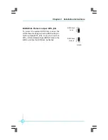
Speaker Connector: SPEAKER
The speaker connector is used to connect
speaker of the chassis.
SPEAKER
1
SPK (Pull high)
SPKJ
Empty
NC
1
+5 V
GND
Empty
S P D I F _ O UT
F_AUDIO
MIC_IN
MIC_PWR
N A
AUD_OUT_L
AUD_OUT_R
MIC_GND
+5VA
AUD_RET_R
E mpt y
AUD_RE T_ L
10
9
2
1
PDF created with pdfFactory Pro trial version
www.pdffactory.com


