background image

Mark the position against

the  outer  edges  of  the

hatches where the servo

arms  will  be,  and  file

3mm wide x 20mm long

slots in the skin for them

as shown. Now you can

glue the mounts into the

wing, with the servos in

place, checking that the

servo arms are centred in

the  slots,  and  parallel

with the wing roots. Use

a  30  minute  epoxy  and

micro-balloons  mixture,

and make sure that they

are properly glued to the skin and to the back of

the wing spar in front of the servo pockets. When

the glue has cured, remove the servos and add

glue to any parts that are not properly bonded,

making sure that they are well fixed to the spar.

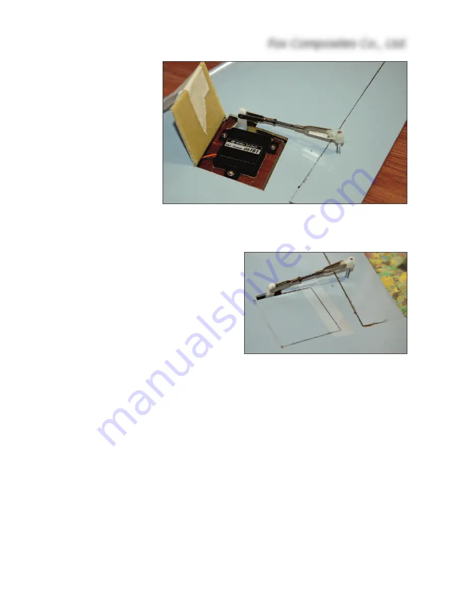
The linkages should be in line with the airflow

(parallel to the wing root), and in practice that is

close enough to the (ideal) 90 degrees to the

elevon  hinge-line  that  it  works  fine.  Tape  the

elevons into the neutral position. Carefully mark

the line (on masking tape) of the linkage, exactly

in line with the servo arms. The control horns are

made from the 35mm lengths of M3 threaded rod,

and there are small plywood blocks installed in-

side the elevons for the horns during manufac-

ture. Drill right thru' the elevons on the marked line, exactly 10mm behind the leading edge, using

a sharp Ø 2.2 or 2.3mm drill. Use a 90° square to keep the drill perpendicular to the bottom sur-

face of the elevators. The holes should be just behind, or against, the balsa elevon L.E. spars.

Thread these holes, right thru' the elevons, using an M3 tap. Sand both ends of the threaded rods

flat, and screw on the plastic adapters provided. Screw them into the tapped holes until the upper

end is flush with the top outer surface of the elevons. The M3 rods are finally secured in place by

applying glue through the open (root) end of the elevons. Apply one drop of thick CA and, when

cured, add a little 30 minute epoxy and micro-balloons mixture.

Make up the linkages using M2 or 2 x 56 clevises and threaded rods. The clevises will need to be

in the servo horn hole approx. 13mm from the servo centre, and the clevise on the elevon horn as

far out as possible - to maximise the mechanical advantage, whilst still obtaining the necessary

maximum elevator throws of 10mm ‘up’. The servo hatches can be held closed with strips of clear

tape. Some small scraps of very thin ply or fibreglass sheet glued inside the corners of the servo

pockets keep the hatches flush with the wing skin.

IMPORTANT

: Do NOT use ball-joints or ball-links on the plastic horn adapters, or plastic servo

arms. They will cause twisting, and almost certain flutter ! 

Fox Composites Co., Ltd.

13

(above)  Completed  elevon  servo  installa-
tion, elevon horn and linkage.
(below) Elastic hinged servo hatches are se-
cured with clear tape for flight.

Содержание ME-163 KOMET

Страница 1: ...Fox Composites Co Ltd February 2008 version 1 0 F Fo ox x C Co om mp po os si it te es s M Me e 1 16 63 3 K Ko om me et t...

Страница 2: ...can be assembled into a fully working and flying radio controlled model airplane when properly fitted with suitable equipment and accessories and constructed ac cording to the current instructions pr...

Страница 3: ...equally important to use high quality glue and to prepare both parts to be joined properly When joining any com bination of fibreglass and wood parts together you must lightly sand both parts to prov...

Страница 4: ...additional photos Currently kits are manufactured in all grey and all red but we may produce a camouflage version later A full list of kit contents including wood parts and hardware is included at th...

Страница 5: ...od quality 3S1P or 4S1P Lipo pack of at least 2200mAH will be fine Ex pect about 3 5 4 5 minute flights with a battery of this capacity We are currently using Kokam 2200 3S and 3200 4S packs Servos Yo...

Страница 6: ...he nose cone which is finally glued onto the fuselage permanently Tip You can wait to glue the nose cone on until the rest of the fuselage is finished which gives easier access when installing the bat...

Страница 7: ...glued into the wings and the front wing joining rod If using the motor and battery packs recommended you will need to posi tion the middle of the battery approx over the front bulkhead centred on the...

Страница 8: ...ized 11 1volt 3S1P battery pack shown is 25 x 25 105mm You can also fit a pair of 2S1P or a 4S1P pack in the same position for increased performance and flight duration When the plane is completed and...

Страница 9: ...happens in flight and you have enough height speed they will usually work again after 10 15 sec onds of cooling and this allows to you make a circuit for landing In this case you know that you will ne...

Страница 10: ...rod keep the canopy in place by pulling it backwards and down wards To remove the canopy you only need to slide it forwards a little until the fibreglass strip disengages from the fuselage and lift i...

Страница 11: ...easiest if the wheel is very narrow approx 10mm 3 8 wide The current factory model has a single wheel fitted into the keel of the fuselage centred about 25mm back from the wing leading edge and this...

Страница 12: ...s during manufacture The middle wing joiner also holds the battery tray into the fuselage passing thru the fibreglass tube that is glued onto the tray At the front of each wing root there is a shorter...

Страница 13: ...re to keep the drill perpendicular to the bottom sur face of the elevators The holes should be just behind or against the balsa elevon L E spars Thread these holes right thru the elevons using an M3 t...

Страница 14: ...he Receiver as far away as possible from the ESC and motor for the least chance of interference We fitted it on the back of the battery tray as shown also with velcro pads and in this case a 2 4GHz sy...

Страница 15: ...ctly on the position of the wing bolts and can easily be checked by hanging the completed model on 2 lengths of thin string from the bolts with the wings pulled slightly away from the fuse lage as sho...

Страница 16: ...especially nice to do and very axial Outside loops are OK but need a little more room so start these with plenty of height for the first few If you fit a rudder then you will find then Komet very neut...

Страница 17: ...uch as I do It reminds me of my Club 20 pylon racing days I am sure you could fit many other makes and types of motor but the ones we have mentioned here are a guide Have fun Jim Kit Contents 1 Fusela...

Страница 18: ...Fibreglass rod 7mm x 85mm anti rotation dowels 1 Fibreglass tube I D 7 x 70mm to secure battery tray 2 Allen bolt M4 x 20mm wing fixing bolts 2 Washers for M4 bolts for above 2 M3 x 35mm threaded rod...

Отзывы: