Fourier Systems Ltd.
16 Hamelacha St., POB 11681, Rosh Ha
‘
ayin 48091,
Tel: +972-3-901-4849, Fax: +972-3-901-4999
www.FourierEdu.com
EXPERIENCE
SCIENCE!
two splitter cables is marked with arrows - that is the main input (the lower I/O
number), the second line is marked with the letter S (split) - indicating that it is the
secondary input (the higher I/O number). Connect up to four input splitters to split the
MultiLogPRO
’
s inputs starting with I/O-4 (the splitters
must
be connected in order):
•
I/O-1 splits into I/O-1 and I/O-8
•
I/O-2 splits into I/O-2 and I/O-7
•
I/O-3 splits into I/O-3 and I/O-6
•
I/O-4 splits into I/O-4 and I/O-5
Note:
Before connecting the mini-din cable to the data logger or the sensor
sockets, make sure that the mini-din plug is correctly positioned in front of the
socket. Connecting the cable in an awkward position might cause damage to the
cable pins.
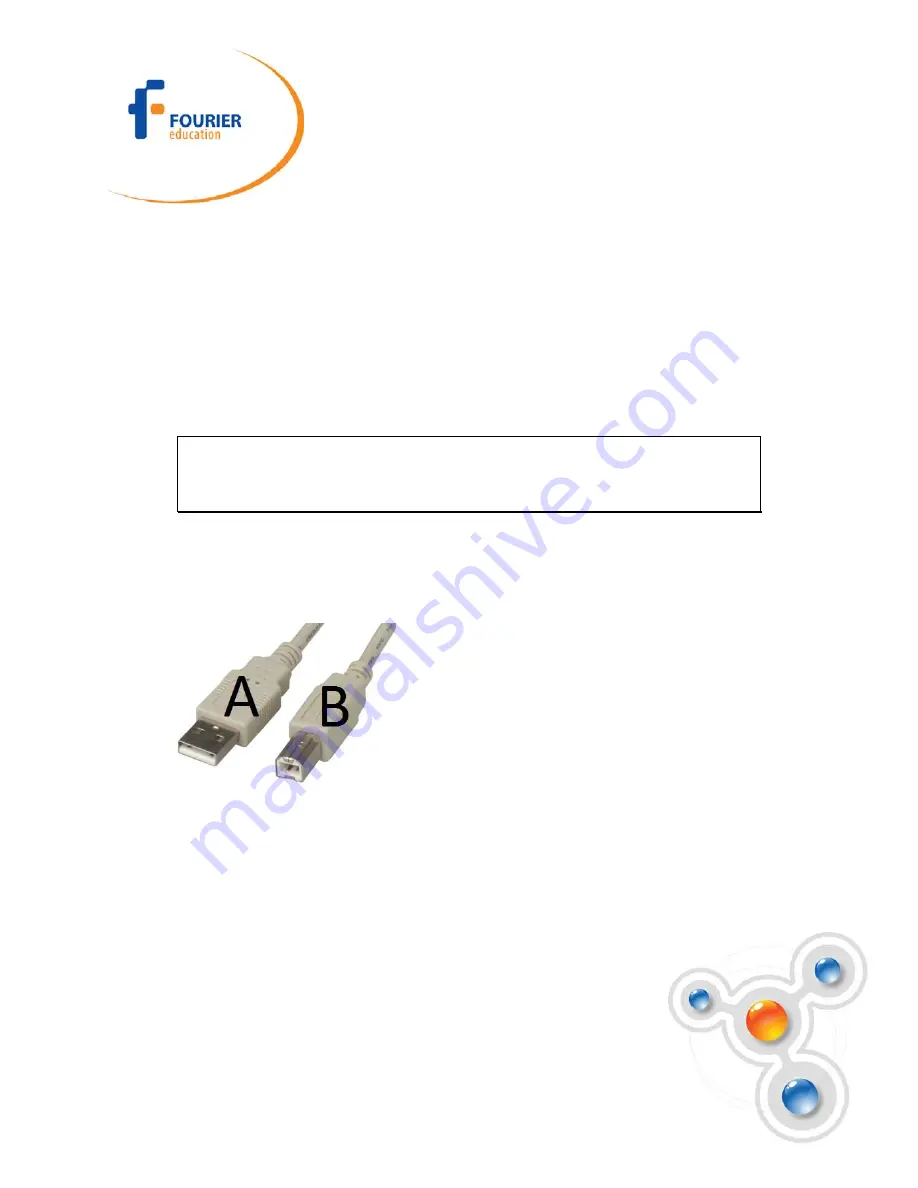
2. Computer USB communication socket
For USB communication between logger and the computer, connect the USB Type B
plug to the MultiLogPRO and the USB Type A plug to the computer.
3. Computer serial communication socket
For Serial communication between logger and computer, connect the 9-pin Type D
cable between this port and one of the computer
’
s COM ports. At the back of the
computer you will find a 9-pin Type D male socket. If your computer is using this port
for the mouse, look for a 25-pin D shell male socket near the mouse. Use the RS-232
9 to 25-pin adaptor to connect the MultiLogPRO serial cable to the 25-pin port (the
adaptor is included with the MultiLogPRO).


