AAØZZ EZKeyer III 23 November 2014
- 7 -
Copyright 2014 AAØZZ
___ Install the 10k potentiometer, R1 in the shims. Insert the 4 signal pins and two side mounting
pins into the shim stack. It sometimes helps to insert the four pot pins first and rotate back on the
two mounting pins. Putting pressure from the side of these pins with a small screwdriver helps
them to seat properly in the holes.
Make sure the shim corner wire connections do not make
contact with the frame of the pot. If one does does, remove the pot and trim the wire/solder
connection and reinstall the pot.
Make sure it is fully seated. Solder all four pins as they enter
the shim. Then solder the two mounting pins into their holes in the shim.
___ Install the 10k trimmer potentiometer, R2. Make sure it is fully seated before soldering. Turn
fully clockwise for maximum volume. Adjust to a comfortable level later.
___ Install the three pushbuttons. Mount them all the way down on the PC board as far as they go.
Solder one switch and align it vertically by sight. If adjustments are needed, fix it by heating one
pin at a time and gradually moving it into position. Similarly, mount and align the other two
pushbuttons. Looking from the side the three pushbuttons should be aligned.
___ Install the PIC in the socket. Orient the notch per the silk-screen on board and the notch in the
socket. To prepare the PIC for installation, hold it by the two ends, turn it on its and side, press
down on a table top so all 9 pins on that side are bent in a bit - until they are pointing straight down.
Turn the PIC over and do the same with the other 9 pins. Now both sets of pins should be aligned
so it will insert easily into the socket.
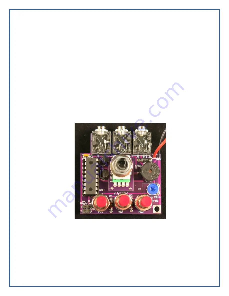
Figure 4.8 – Completed Board
___ Consider whether or not you want to use the speed-limit jumpers (HDR1). See the Speed
Limits description in Section 7.4. You can always change it later, of course, but it's easier to do
before you install the board in the case.
___ Set the trimmer pot, R2, to desired speaker volume setting. As a starting point, turn it to
maximum volume (clockwise). If you are using the onboard piezo you will probably like it in the
maximum volume position. If you are using one of the external speakers you may want to turn it
back a bit after testing in the case.
Figure 4.8 shows the completed PC Board.


