background image


1


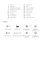
Console 


73 

Induction cord 

3


Handlebars 


79 

Seat 

7


Handlebar cover (upper) 


82 

Power cord (lower) 

8


Handlebar cover (lower) 


85 

Right foot pedal 

10


Handlebar post 


89 

Left foot pedal 

15


Pull pin 


92 

13-15 Spanner 

17


Frame base 


93 

Allen key 1 

29


Front stabiliser 


94 

Allen key 2 

68 

Rear stabiliser 


95 

Power cord (upper) 


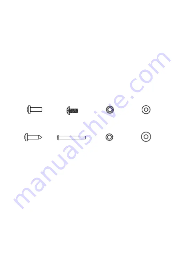
Hardware: 


2

 M8x10L (x4) 

4

 M8x12L (x4) 

5

 Spring Washer 

Ø9 (x4) 

6

 Washer 

Ø8xØ16x1.6T (x4) 


9

 ST4.0x15L (x4) 

34

 M10x65LxS15 (x4) 

35

 Spring Washer 

Ø10.5 (x4) 

36

 Washer 

Ø10xØ20x2T (x4) 


Содержание SK-2200A

Страница 1: ...AUTOMATIC VARIABLE RESISTANCE MAGNETIC FLYWHEEL SPIN BIKE SK 2200A FSEMSB2200A...

Страница 2: ......

Страница 3: ...the equipment This equipment is designed for consumer use Follow directions and use only as described Once fully assembled inspect to ensure all hardware parts such as bolts nuts and washers are posi...

Страница 4: ...freely and possibly hurt someone while bike is not in use Do not exceed the maximum user weight of 100 KG Be careful when lifting and moving the equipment Always use proper lifting technique and seek...

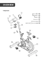
Страница 5: ...Components OVERVIEW...

Страница 6: ...edal 10 Handlebar post 89 Left foot pedal 15 Pull pin 92 13 15 Spanner 17 Frame base 93 Allen key 1 29 Front stabiliser 94 Allen key 2 68 Rear stabiliser 95 Power cord upper Hardware 2 M8x10L x4 4 M8x...

Страница 7: ...Step 1 Attach the front and rear stabilisers 29 68 using the screws washers and spring washers 34 35 36 and Allen Key 93 shown below ASSEMBLY...

Страница 8: ...Step 2 Attach the seat 79...

Страница 9: ...Step 3 Attach the 82 95 wiring then fit the handlebar post 10...

Страница 10: ...Step 4 Set the handlebar post into position with the Pull pin 15...

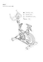
Страница 11: ...Step 5 Attach the handlebars 3...

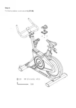
Страница 12: ...Step 6 Fit the handlebar cover assembly 7 8...

Страница 13: ...Step 7 Fit the Console 1...

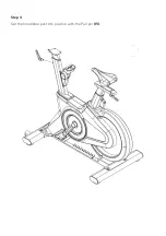
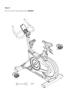
Страница 14: ...Step 8 Attach the left and right pedals 85 89...

Страница 15: ...s and enter the program DOWN Increase the selected training mode Decrease selected value RECOVERY Test heart rate recovery Data Display Range TIME Display range 0 00 99 99 Set the range from 0 00 to 9...

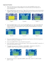
Страница 16: ...o set a time Figure 4 Press the MODE button and use the UP DOWN buttons to adjust the distance Figure 5 Press the MODE button then press the UP DOWN button to set the calories Figure 6 Figure 4 Figure...

Страница 17: ...ion TIME can only be adjusted in BEGINNER ADVANCE SPORTY WATT HRC modes 4 CARDIO Heart Rate Controlled H R C Options In the CARDIO H R C mode press the MODE button to display the preset value in the P...

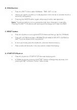
Страница 18: ...se program has begun will have no effect C RESET button Press this button once in system STOP state and then go back to MANUAL Press UP or DOWN to select BEGINNER ADVANCE SPORTY CARDIO or WATT and all...

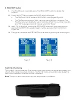
Страница 19: ...emit a Beep 3 After FX is displayed pressing the RECOVERY button will restore the general display If this BUTTON is pressed again it will be executed from the first item Figure 10 4 During the countd...

Страница 20: ...mmediately and do not use the equipment again until it is in perfect working order The equipment can be cleaned using a damp cloth and mild non abrasive detergent Do not use solvents Do not attempt to...

Страница 21: ...NOTES...

Страница 22: ......

Страница 23: ......

Страница 24: ...ion We hope that this user guide has given you the assistance needed for a simple set up For the most up to date guide for your product as well as any additional assistance you may require head online...

Отзывы: