FORCE COMPUTERS
Page 27
SSPARC/CPU-5CE
Installation Guide
1.8.2
Serial Ports A and B Connector Pinout
The two serial I/O ports are available on the front panel via two 26-pin shielded connectors
which are compatible to the CPU-2CE and to the CPU-3CE.
Both channels are available via the VMEbus P2 connector, each with four signals (RXD,
TXD, RTS, CTS). Each of the two serial I/O ports are independent full-duplex channels. The
table below shows the pinout of serial ports A and B. The table is valid for both serial I/O
connectors A and B.
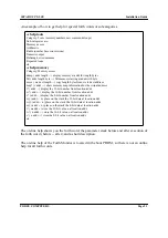
FIGURE 7.
Serial Ports A and B Connector Pinout
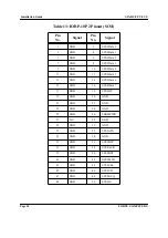
Table 9: Serial Ports A and B Connector Pinout for RS-232
Pin
Transmitted Signals
Pin
Received Signals
2
TxD-Transmit Data
3
RxD-Receive Data
4
RTS-Request To Send
5
CTS-Clear To Send
7
GND
6
SYNC
20
DTR-Data Terminal Ready
8
DCD-Data Carrier Detect
24
TRXC-DTE Terminal Clock
15
TRXC-DCE Terminal Clock
17
RTXC-DCE Terminal Clock
1
13
14
26
Содержание SPARC CPU-3CE
Страница 4: ...Table of Contents SPARC CPU 5CE Installation Guide Page ii FORCE COMPUTERS...
Страница 6: ...List of Figures SPARC CPU 5CE Installation Guide Page iv FORCE COMPUTERS...
Страница 8: ...List of Tables SPARC CPU 5CE Installation Guide Page vi FORCE COMPUTERS...
Страница 11: ...FORCE COMPUTERS Page 3 SSPARC CPU 5CE Installation Guide FIGURE 1 Diagram of the CPU 5CE...
Страница 48: ...Installation Guide SPARC CPU 5CE Page 40 FORCE COMPUTERS...

