EN
- 5 -
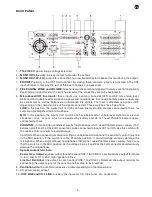
BACK PANEL
1.-
115 V/230 V
: power supply voltage selection.
2.-
MONITOR (Line out)
: line level output to monitor the output.
3.-
MONITOR (1 W, 8 Ω):
output for connection to a low impedance 8Ω speaker for monitoring the output.
4.-
PRIORITY:
priority in the CH1 input channel. By closing these contacts, priority is activated in the CH1
input channel. In this way the rest of the input channels are weakened.
5.-
TEL. PAGING
,
ZONE and VOLUME:
telephone switchboard input signal with volume control and priority
depending on signal level with 4 switches to select the zones they are to be assigned to.
6.-
Microphone/CH1 line inputs:
these inputs use a combi connector (XLR and 6.3 mm stereo jack).
Balanced and unbalanced microphone signals and microphones that need phantom power supply can
be connected, as well as balanced or unbalanced line signals. The input is adjusted using the switch
depending on the characteristics of the signal connected. These switches have 3 positions:
LINE
: in this position, the inputs CH1 to CH3 can have line level audio sources connected to them, for
example a preamplified table microphone.
MIC
: in this position, the inputs CH1 to CH3 can have balanced or unbalanced, dynamic or electret
condenser mics., or mics. which are powered by battery and do not need Phantom power supply,
connected to them.
PHANTOM
: in this position condenser electret microphones which need Phantom power supply (15 V
between pins 2 and 3 of the XLR connector) can be connected to inputs CH1 to CH3. Use this switch with
the volume at its minimum to avoid damage.
CAUTION: When connecting or disconnecting an unbalanced microphone the sensitivity switch must be
in the MIC position. If the switch is in the Phantom position, it could damage seriously damage the
microphone. When using balanced microphones that do not need Phantom power supply, make sure
that the switch is in the MIC position, as the voltage in pins 2 and 3 of the XLR connector could seriously
damage the microphones.
7.-
Speaker output terminals:
Power Amp. Output
: speaker output for each zone (ZONE 1 to ZONE 4). Low impedance output terminals
(4 -8 Ω) and 100, 70, 25 V high impedance lines.
Line Out Bal/Unbal
: line output for each zone (ZONE 1 to ZONE 4). Balanced line output terminal for
connecting the output signal of the zone to another amp to be amplified.
8.-
Ventilation slits:
the ventilator speed is variable depending on the temperature.
9.- AC power supply socket.
10.-
CH 5 LINE and CH 4 LINE
: auxiliary line inputs for CD, tape, tuner, etc. connection.
Содержание MAZ-4160
Страница 1: ...MAZ 4160 MULTIZONE AMPLIFIER WITH 4 OUTPUT ZONES EN Instruction Manual...
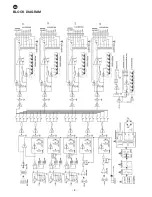
Страница 8: ...8 EN BLOCK DIAGRAM...


