
FGI-011_Rev.D 08/10/2015 Qwik-Fence Installation Instructions
5858 W. 73
RD
ST
BEDFORD PARK, IL. 60638
Qwik-Fence
®
15
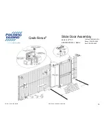
Slide Door Assembly
Toll Free: (800) 622-2214
Phone: (708) 325-0400
Fax: (708) 325-0450
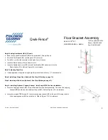
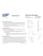
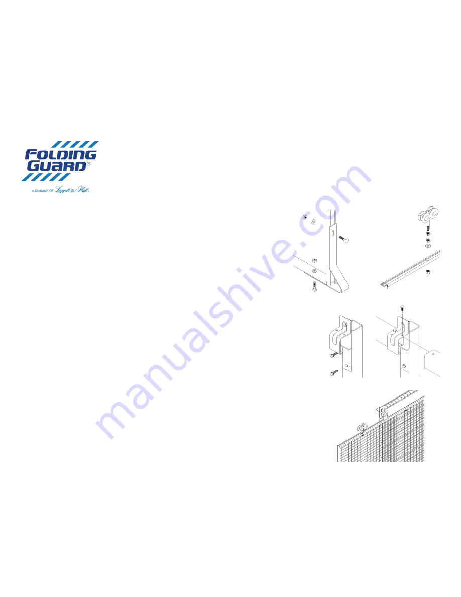
Step 9B: Slide Door Pre-Assembly.
Attach the Guide (B8) to the bottom back end of the door with provided Carriage Bolt (F2)
and Nut (F3), as shown in Figure (9B-1).
Attach the Trolley assembly (B9) to the top of the door by inserting it into the existing holes
at the top of the door. For reference use Figure (9B-2).
Fig.
9B
‐
2
Fig.
9B
‐
1
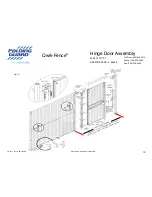
Step
9C:
Slide
Channel
Assembly
&
A achment.
Take
the
slide
door
bracket
assembly
(
Step
9A
)
and
a ach
it
through
the
bo om
two
holes
via
a
TEK
Screw
(F1)
and
a
Washer
(F4).
Refer
to
Figure
(9C
‐
1)
for
visual
instruc ons.
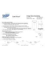
Insert
the
Slide
Door
Track
inside
the
Slide
Door
Bracket
Assembly
as
shown
in
Figure
9D
‐
2.
Tighten
the
bolts
on
top
of
the
Slide
Door
Bracket
(B4)
through
the
holes
in
the
Slide
Door
Track
(D6).
Refer
to
Figure
(9C
‐
2)
for
Visual
Instruc ons.
(NOTE:
The
holes
DO
NOT
have
to
be
aligned,
however
make
sure
the
gap
between
channels
is
minimal)
If
your
Ver cal
Post
height
is
taller
then
96”
DO
NOT
a ach
the
Slide
Door
Bracket
(B4)
to
the
Slide
Door
Moun ng
Strip
(B5).
Instead
Measure
96”
from
the
ground
to
the
bo om
of
the
Slide
Door
Bracket
(B4)
and
using
a
TEK
screw
(F1)
and
(F4)
washer
a ach
directly
to
post.
Fig.
9C
‐
2
Fig.
9C
‐
1
Fig.
9D
‐
1
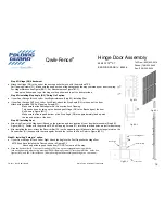
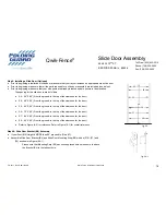
Step
9D:
Slide
Door
Assembly.
Take
the
Assembled
door
(
Step
9C
)
and
insert
the
trolleys
into
the
Slide
Door
Track
(D6).
See
Figure
9D
‐
1
for
reference.
Slide
the
door
all
the
way
through.
Make
sure
that
that
door
moves
freely
with
in
the
Slide
Door
Track
(D6).
Make
sure
there
is
a
2”
clearance
between
the
bo om
of
the
door
and
the
fl
oor.
If
there
is
not
adjust
the
trolleys
un l
there
is.
Please
note
that
when
inser ng
the
door
assembly
the
front
of
the
door
should
go
in
fi
rst
and
that
the
lock
should
be
facing
towards
the
direc ons
that
is
speci
fi
ed
in
the
Plan
Drawings
either
provided
by
Folding
Guard®
or
Your
Company’s
Representa ve.
A er
Inser ng
the
Door,
please
insert
the
Stop
Bolt
(F12)
into
the
free
hole
in
the
Slide
Door
Track
Assembly
on
the
back
end
of
the
door,
and
Tighten
with
Nut
(F3).
This
will
prevent
the
door
from
sliding
out
of
the
Slide
Door
Track
(D6).
CAUTION:
Door
Stop
Bolt
must
be
installed
in
order
to
prevent
the
door
from
exi ng
the
track.