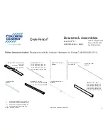

FGI-011_Rev.D 08/10/2015 Qwik-Fence Installation Instructions
Toll Free: (800) 622-2214
Phone: (708) 325-0400
Fax: (708) 325-0450
5858 W. 73
RD
ST
BEDFORD PARK, IL. 60638
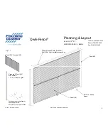
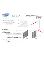
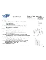
Qwik-Fence
®
12
Hinge Door Assembly
Fig.
8C
‐
1
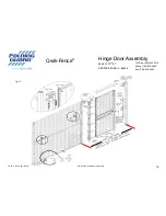
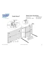
Step 8C: Hinge (D2) Attachment
Attach the Hinge (D2) to the end of the door opposite the lock, with the provided TEK
Self Tapping Screws (F1). Make sure the bend portion of the swing faces the way you intend your door to swing.
For Hinge reference use Figure (8B-1). For Attachment see Figure (8C-1).
Line up the bottom and top of the hinge to the bottom and top of the door provided.
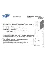
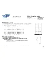
Step 8D: Installing Stop Angle (D3) “Swing Out” option.
If your Door Swings IN Lock Left or Lock Right reference (
Step 8E
): Installing Door.
If your Door Swings OUT Lock Left or Lock Right, attach the Stop Angle (D3) to the end of the door.
Attach with provided TEK Self Tapping Screws (F1).
Make sure that the Rectangular Slot fits over the Lock Opening
This can be done by lining up the back edge of Hinge (D2) to the Back edge of the door.
As Shown in Figure (8D-1).
Make sure that the top and bottom of the Stop Angle (D3) are approximately lined up with
the top and bottom of the door.
Fig.
8E
‐
1
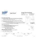
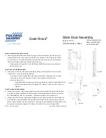
Step 8E: Installing Door.
Attach the Door to the Hinge post (Based on the direction and lock location of your door determined in (
Step 8B
),
Figure (8B-1)). Fasten with the provided TEK Self Tapping Screws (F7) into the pre-drilled holes; adjust for best swing.
After installing the door, attach the Receiver Bar (D1) on the opposite post. (Make sure that the rectangular slot on the
Receiver Bar (D1) lines up with the rectangular slot and the lock on the Door. Refer to Figure (8E-1))
Fig.
8D
‐
1
Fig.
8F
‐
1
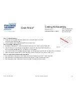
Stop
Angle
Exis ng
Door
Receiver
Bar
Lock
Post
Step 8F: Installing “Swing In” option.
If your Door Swings IN Lock Left or Right Attach the Angle to the Post Opposite the Hinge Post
AFTER you have Installed the Door as shown in Figure 8F-1
Attach only at the top and the bottom, DO NOT screw in all the way.
Place
the
Receiver
Bar
(D1)
on
top
of
Stop
Angle
(D3),
line
up
the
rectangular
opening
with
the
lock
on
the
door
and
a ach
using
provided
TEK
Self
Tapping
Screws
(F1)
into
the
pre
‐
drilled
holes.
Use
Figures
(8F
‐
1)
and
(8E
‐
1)
for
reference.
(A er
ensuring
that
all
assembly
parts
fi
t
ghten
the
screws).