background image

                           FS-MG41

Digital Proportional Radio Control System

14

This equipment has been tested and found to comply with the limits for a Class B digital device pursuant to part 
15 of the FCC rules. These limits are designed to provide reasonable protection against harmful interference in a 
residential installation. This equipment generates, uses and can radiate radio frequency energy and, if not installed 
and used in accordance with the instructions, may cause harmful interference to radio communications. However, 
there is no guarantee that interference will not occur in a particular installation. If this equipment does cause 
harmful interference to radio or televison reception, which can be determined by turning the equipment off and on, 
the user is encouraged to try to correct the interference by one or more of the following measures:

•  Reorient or relocate the receiving antenna.
•  Increase the separation between the equipment and receiver.
•  Connect the equipment into an outlet on a circuit different from that to which the receiver is connected.
•  Consult the dealer or an experienced radio/TV technician for help.

To assure continued compliance, any changes or modifications not expressly approved by the party responsible for 
compliance could void the user's authority to operate this equipment. 

This equipment complies with Part 15 of the FCC Rules. Operation is subject to the following two conditions:
(1) This device may not cause harmful interference.
(2) This device must accept any interference received, including interference that may cause undesired operation.

Caution!
The manufacturer is not responsible for any radio or TV interference caused by unauthorized modifications to this 
equipment. Such modifications could void the user authority to operate the equipment.
1.  The antenna(s) used for this transmitter must be installed to provide a separation distance of at least 20 cm 

from all persons and must not be co-lacated or operating in conjunction with any other transmitter.End-users 

and installers must be provided with antenna installation instructions and transmitter operating conditions for 

satisfying RF exposure compliance.

2.  Move all your channels to the desired position.
3.  Select [All channels] and then [Yes] in the confirmation box. 

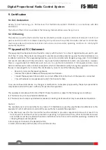
9. Certification 

9.1 DoC Declaration

9.2 CE Warning

The antenna(s) used for this transmitter must be installed to provide a separation distance of at least 20 cm from all 
persons and must not be co-located or operating in conjunction with any other transmitter. End-users and installers 
must be provided with antenna installation instructions and transmitter operating conditions for satisfying RF 
exposure compliance.

9.3 

Appendix 1 FCC Statement 

Hereby, [Flysky Technology co., ltd] declares that the Radio Equipment [FS-MG41] is in compliance with RED 
2014/53/EU.
The full text of the EU DoC is available at the following internet address: www.flysky-cn.com.

All manuals and user guides at all-guides.com

Содержание FS-MG41

Страница 1: ...FS MG41 Copyright 2021 Flysky Technology co ltd USER MANUAL Digital Proportional Radio Control System All manuals and user guides at all guides com...

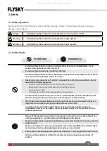
Страница 2: ...your safety and the safety of others read this manual carefully before using this product If you encounter any problem during use refer to this manual first If the problem persists contact your local...

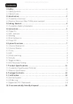
Страница 3: ...tion 6 4 5 Power Off 6 5 System Functions 7 5 1 Channel Description 7 5 2 Channel Reverse 7 5 3 Trims 7 5 4 D R 8 5 5 Mode switching 8 5 6 Failsafe 8 5 7 Beginner Mode 9 5 8 ESC Parameter Setting 9 7...

Страница 4: ...not operate in the following places Near any site where other radio control activity may occur Near power lines or communication broadcasting antennas Near people or roads On any body of water when pa...

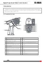
Страница 5: ...1 Transmitter Overview 1 2 3 4 5 6 7 13 12 14 16 15 17 18 8 9 11 10 1 Traversing handwheel 35 degrees on each side CH1 10 ST D R 2 Throttle button 25 degrees in front and 12 5 degrees at rear CH2 11 T...

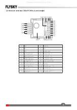
Страница 6: ...Light port 15 Battery line 5 Right Light port 16 Motor line M 6 Head Light port 17 Motor line M 7 Tail Light port 18 Power switch line 8 Ambient Light port 19 Stickers 9 Roof Light port 20 Channel por...

Страница 7: ...r expose to strong shocks or vibrations Danger Always store the battery in a cool dry place Danger Do not use the battery if damaged Battery Type AAA Battery Installation 1 Open the battery compartmen...

Страница 8: ...de first then the receiver 4 1 Power On However if the receiver needs to be replaced or additional receivers bound follow these steps Note Operate with caution in order to avoid damage or injury Note...

Страница 9: ...letely clockwise then completely counterclockwise When calibration is completed the R LED will be off Car Battery the D3 red keeps on 3 Trigger calibration Pull the trigger back then forward as far as...

Страница 10: ...the servo or motor The ST REV TH REV switches are the reverse buttons for CH1 and CH2 If the switch is up it indicates reverse and the down indicates normal 5 3 Trims The ST TRIM is the trims for CH1...

Страница 11: ...fault mode 1 is used Mode 1 R LED is always on G LED is off ST TRIM is for CH1 trim ST D R is for CH1 servo adjustment TH TRIM is for CH2 throttle trim TH D R is for CH2 throttle servo adjustment Mode...

Страница 12: ...tches numbered 1 2 3 4 on the radio panel The above parameters can be set by dialing down and up The specific operation is as follows When No 1 slide switch is on the down it indicates that the operat...

Страница 13: ...e protection value is different under different types It can be set according to the actual use Parameter setting method When No 2 slide switch is on the down it indicates that the battery type is set...

Страница 14: ...rature Range 10 60 Humidity Range 20 95 Online Update No Color Black size 118 73 145mm weight 1300g Certification CE FCC ID N4ZMG400 7 2 Receiver Specification FS R4A Product Model FS R4A Main applica...

Страница 15: ...nnector 22 1g with small TAMIYA male connector size 34 25 15 5mm Certification CE FCC ID N4ZHW 709 Product Model HW 711 Applicable motor 280 370 brushed motor 12T or RPM 30000 7 4V Main applications 1...

Страница 16: ...13 8 Package Contents Transmitter 1 FS MG41 Receiver 1 FS R4A All manuals and user guides at all guides com...

Страница 17: ...he following two conditions 1 This device may not cause harmful interference 2 This device must accept any interference received including interference that may cause undesired operation Caution The m...

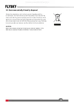
Страница 18: ...s for free The owner of old appliances is responsible to bring the appliances to these collecting points or to similar collection points With this little personal effort you contribute to recycle valu...

Страница 19: ...Copyright 2021Flysky Technology co ltd www flysky cn com Release date 2021 04 17 FCC ID N4ZMG400 FCC ID N4ZR4A00 All manuals and user guides at all guides com...

Отзывы: