


32/68
Original Operating Instructions Eccentric worm drive pump F 550 and Sanitary Pump F 560
ENGLI
SH
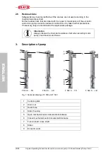
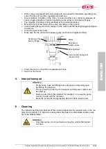
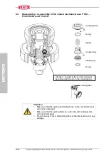
4.3
Equipotential bonding
If the motors are operated together with the pump, comprehensive, clear equipotential
bonding is essential (earthing, Fig.1)
> Connect the earth continuity conductor (earth wire) to the designated screw on the
explosion-proof motor.
> Connect the earth continuity conductor (earth wire) to the designated screw on the
pump. For equipotential bonding, an electrically conductive connection must be pro-
duced between the motor and the pump according to DIN EN 60079-0 and DIN EN
60079-14. If the connection between the motor and pump already provides a conductive
path one of the equipotential bonding conductors may be dispensed with.
> The containers should be grounded separately (3), if they are not already grounded by
the mode of installation.
> The hose connected with the pump must not exceed a resistance of 10
6
Ohm between
the hose ends. Only use hose lines with conductive hose unions (see TRbF 50 Annex
B, R < 10
6
Ω
). This will provide a conductive path for the pump, hoses and fittings.
> Only use an explosion-proof plug or an explosion-proof terminal box when making
connections to the mains or outside the hazardous area.
> Remove paint and dirt from all connection points of equipotential bonding conductors
and transition points of the containers to the electrically conductive base ground to
ensure good conductivity.
The electrically conductive base ground must be an integral part of the equipotential bond-
ing system.
If a conductive base ground is not available, equipotential bonding conductors must be
connected to all drums and containers.
Note
Explosion protection at the connection point is not necessary if the
power socket or the terminal box is clearly located outside the
hazardous area.
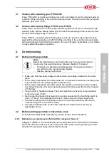
4.4
Commissioning of version with planetary gear F 550 GS6
Driven by three-phase motor F 403
> Mount the horizontal version of the pump completely in the system.
> Put the motor onto the pump.
> Firmly tighten union nut by hand.
> Insert the plug or connect the air supply hose.
> Switch on the motor.
4.5
Commissioning of version with bearing flange F 550 S and F 560 S
Available drive motors:
Three-phase motors 0.75 to 1.1 kW, 700 or 930 rpm
Compressed air motors FPM 4 Ex, FPM 6 Ex, FPM 8 Ex, maximum speed
1000 rpm.
Attention!
Installation, maintenance and repairs to three-phase motors should
only be carried out by suitably qualified personnel.
>
Only
use three-phase motors with a starter including an overload cut-out switch.
> Make sure that the supply voltage corresponds to the voltage indicated on the name
plate.
Содержание F 550 GS6 Series
Страница 63: ...63 68 13 EG EU Konformitätserklärung EC EU Declaration of conformity Déclaration de conformité CE UE ...
Страница 64: ...64 68 ...
Страница 65: ...65 68 ...
Страница 66: ...66 68 ...
Страница 67: ...67 68 ...
Страница 68: ...FB 10 56083003_00_TR_0816 1 DEF ...