OPERATING INSTRUCTIONS
23
Side channel blower
Version: 27222 - C
Schmalenberger GmbH + Co. KG
D-72072 Tübingen / Germany
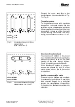
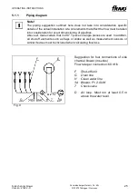
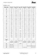
Fig. 7:
Connection diagram for three-
phase motors;
Delta connection
∆
Connect the motor according to the
circuit diagram in the terminal box or Fig.
7 or Fig. 8.
Time relay setting
For three-phase motors with star-delta
connection, you must ensure that the
switching points between star and delta
follow one after the other in as little time
as possible. Longer switching times will
result in damage to the motor. Time delay
setting for star-delta connection: < 3 sec.
Fig. 8:
Connection diagram for three-
phase motors, star circuit Y
Direction of rotation check
The direction of rotation of the motor
must match the direction indicated by the
direction of rotation arrow on the spiral
housing of the side channel blower.
Check by switching on and off briefly.
If the direction of rotation is incorrect,
reverse two phases L1, and L3 of the
mains power supply line in the motor
terminal box.
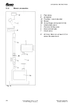
Auxiliary equipment for motor
If special control devices are provided,
for example in conjunction with use of the
side channel blower in a technical
system, the manufacturer's instructions
for these control devices must always be
observed.
230 V /
≤≤≤≤
3 kW
400 V /
>>>>
3 kW
400 V /
≤≤≤≤
3 kW
690 V /
>>>>
3 kW

