


i400s
Calibration Information
4
Input Load Impedance (of host instrument):
> 1 M
Ω
in parallel with up to 47 pF
Maximum Non-destructive Current:
1000 A
Duty Cycle:
0.5 A to 400 A continuous
Influence of Adjacent Conductor:
< 9.0 mA/A
Influence of Conductor Position in Jaw Opening:
±
1.0 % of r 0.05 A
General Specifications
Output Cable Length:
2.5 m (8.2 ft)
Maximum Conductor Size
: 32 mm (1.25 in)
Storage Temperature:
-20
°
C to 60
°
C (-4
°
F to 140
°
F)
Operating Temperature:
0
°
C to 50
°
C (32
°
F to 122
°
F)
Relative Humidity:
10
°
C to 30
°
C: 95 % (50
°
F to 86
°
F)
30
°
C to 40
°
C: 75 % (86
°
F to 104
°
F)
40
°
C to 50
°
C: 45 % (104
°
F to 122
°
F)
Temperature Coefficient:
0.01 % X (specified accuracy)/
°
C (< 18
°
C or > 28
°
C)
0.01 % X (specified accuracy)/
°
F (< 64.4
°
F or > 82.4
°
F )
Altitude:
Operating: 2000 m; 2000 m to 4000 m, derate category rating to 1000 V CAT II/600 V CAT III
Non-operating: 12000 m
Dimensions:
(LxWxH) 150 x 70 x 30 mm (5.09 x 2.75 x 1.18 in)
Weight:
114 g (4 oz)
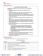
Maintenance
XW
Warning
To avoid possible electric shock or personal injury:
•
Before each use, inspect the Current Clamp. Look for cracks or missing
portions of the clamp housing and output cable insulating cover and for
loose or weakened components. Pay particular attention to the insulation
surrounding the clamp jaws.
•
Do not use a damaged Current Clamp. If a clamp is damaged, tape it shut to
prevent unintended operation. A damaged clamp under warranty will be
promptly repaired or replaced (at Fluke’s discretion) and returned at no
extra charge.
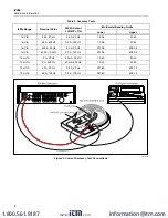
If the Current Clamp does not work or perform properly, use the following steps to help isolate the
problem:
1.
Inspect the jaw-mating surface for cleanliness. If any foreign material is present, the jaw will not
close properly and measurement errors will result.
2.
Verify that the function selection and range on the Multimeter are correct and adjusted to the
sensitivity of the Current Clamp.
www.
.com
1.800.561.8187


