
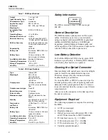


FOM/FOS
Service Information
4
3.
Tuck the battery wires down against the pca so
they will not interfere with SW1.
4.
Set SW1 to the off position.
5.
Set the slide switch actuator on the top case to
the OFF position. For the FOS, place the
lanyard into the notch in the bottom case.
6.
Put the top and bottom cases together; then
replace the two screws under the battery door.
Calibration Adjustments for the
FOM
To ensure that the FOM performs to specifications,
calibrate it annually using the procedure that
follows.
Always perform the complete calibration
adjustment procedure.
Preparing for Calibration
To prepare for calibration, proceed as follows:
1.
Remove the dust cap from the FOM.
2.
Connect a voltage supply of 8V ±1.0V dc to the
FOM battery strap.
3.
Set the FOM switch to the 1300 nm position.
Allow the FOM to warm up for 10 minutes.
4.
Allow all sources to warm up according to the
manufacturer’s specifications.
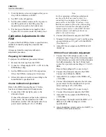
Coarse Calibration Adjustment
Refer to the FOM drawing (Figure 1) for the
locations of measurements and components.
1.
Connect the 1300 nm light source to the
attenuator input.
Connect the attenuator output to the reference
power meter. Set the attenuator for 0 dB
attenuation. Set the 1300 nm light source for a
power meter reading of -10 ± 0.05 dBm.
Note
For the remaining calibration adjustments,
use the cable that was used in step 1 for
connecting the attenuator to the reference
power meter or the FOM. To reduce errors,
limit the movement of the cable when making
connections between the attenuator and the
reference power meter or the FOM. To limit
cable movement, coil and tape the excess
cable to the work surface.
2.
Connect the attenuator output to the FOM.
3.
Measure Vdet between U1 pin 7 and the analog
ground reference at U1 pin 5 with the DMM.
(See Figure 1.)
4.
Adjust R2 for an output on the DMM of 0.23
±
0.01V dc.
1300 nm Fine Calibration Adjustment
1.
Connect the 1300 nm light source to the
attenuator input. Connect the attenuator output
to the reference power meter. Set the attenuator
for 0 dB attenuation. Set the 1300 nm light
source for a power meter reading of -10 ±0.05
dBm.
Record this reading as Po to use in step 3.
2.
Connect the attenuator output to the FOM.
Connect the FOM to the DMM.
3.
Adjust R10 for an output on the DMM of Po
±0.05 dBm.
4.
Connect the attenuator output to the reference
power meter. Set the attenuator for a power
meter reading of -45 ±0.05 dBm.
Record this reading as Po to use in step 6.
5.
Connect the attenuator output to the FOM.
6.
Adjust R2 for an output on the DMM of Po
±0.05 dBm.
7.
Repeat steps 1 through 6 until the FOM’s -10
dBm and -45 dBm readings are within
specifications.
8.
Apply insulating varnish, such as red GLPT, to
the R10 and R2 potentiometers.


