
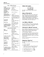


Fiber Optic Meter/Source
Performance Tests
3
•
2 ST/ST multimode fiber optic patch cables
The following equipment is required for servicing
the FOS:
•
Calibrated FOM
•
Digital multimeter
•
One ST/ST multimode fiber optic patch cable
Performance Tests
Use the following performance tests to confirm that
the FOM or FOS is working properly. If the FOM
or FOS fails any of these tests, it needs calibration
adjustments or repair.
FOM -10 dBm Checkout
1.
Turn on the FOM and the three light sources.
Allow the FOM to warm up for 10 minutes.
Allow the sources to warm up according to the
manufacturer’s specifications.
Perform the remaining steps using the light
sources in the following order: (1) 850 nm, (2)
1550 nm, and (3) 1300 nm.
2.
Connect the light source to the reference power
meter using a fiber optic patch cable.
3.
Adjust the output of the source for a power
meter reading of -10.00
±
0.05 dBm. Record this
reading as Po (power out) to use in step 5.
4.
Set the FOM switch to the wavelength position
being tested.
5.
Connect the FOM to the light source using the
patch cable from step 2.
Allow a few seconds for the reading to
stabilize; then verify that the reading is Po
±
0.25 dBm.
6.
Disconnect the light source from the FOM.
FOM -50 dBm Checkout
1.
Connect the 1300 nm light source to the optical
attenuator.
Connect the attenuator to the reference power
meter using a second fiber optic patch cable.
2.
Set the optical attenuator for a power meter
reading of -50.00
±
0.05 dBm. Record this
reading as Po to use in step 4.
3.
Connect the FOM to the attenuator using the
patch cable connected to the reference power
meter.
4.
Allow a few seconds for the reading to
stabilize; then verify that the reading is Po
±
0.4
dBm.
5.
Turn off the DMM, FOM, and the light sources.
Disconnect the FOM from the DMM.
Disconnect the fiber optic patch cables from the
attenuator, source, and FOM.
FOS Checkout
1.
Connect the FOS to the calibrated FOM with a
patch cable.
Turn the FOS on to the wavelength being tested
and let it stabilize for 20 minutes.
2.
Connect the FOM to a DMM with at least
0.1 mV resolution.
Turn the FOM on and set the switch to the
wavelength being tested.
3.
Verify that the FOS output is -20
±
0.5 dBm
(-19.5 to -20.5 mV on the DMM).
4.
For a dual source, repeat steps 1 through 3 for
each wavelength.
Disassembling and Reassembling
the FOM and FOS
To perform calibration adjustments for the FOM
and the FOS, you must disassemble them. When
you finish the adjustments, reassemble them. A
Phillips-head screwdriver is required for
disassembling and reassembling the FOM and FOS.
To disassemble the FOM or FOS, proceed as
follows:
1.
Set the FOM or FOS switch to OFF.
2.
Remove the battery door; then disconnect the
battery.
3.
Remove the two Phillips screws found under
the battery door; then separate the top and
bottom cases.
4.
To remove the pca, remove the Phillips screw
near SW1; then lift out the pca.
To reassemble the FOM or FOS, proceed as
follows:
1.
Reinsert the pca; then replace the screw that
holds the pca.
2.
Tuck the battery wires into the notch at the side
of the battery compartment.


