


FOM/FOS
Service Information
2
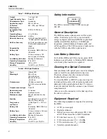
Table 1. FOM Specifications
Output
1 mV per 1 dB
Input Connector Type
Fixed ST
Photodetector Type
Germanium
Application range
800 to 1600 nm
Calibrated
Wavelengths
850, 1300, and 1550 nm
Acceptable Fiber
Types
9/125 to 100/140
µ
m
Operating Range
+3 to -50 dBm
Maximum Power Level
+5 dBm
Absolute Accuracy
±
0.25 dB (specified at 25
°
C
-10 dBm per NIST standard)
Relative Accuracy
±
0.15 dB, (specified over any
10 dB within measurement
range)
Repeatability
±
0.04 dB
Battery Life
9V alkaline, NEDA 1604A or
IEC 6LR61
Battery Type
16 hours minimum, 100
hours typical, 9V alkaline
Low Battery Indication
Blinking LED indicator
Operating Temperature
0
°
to +40
°
C
Storage Temperature
-20
°
to +70
°
C
Humidity
0 to 40
°
C up to 75% RH
Table 2. FOS Specifications
Type
Infrared LED
Wavelength
850
±
30 nm
1300 -40/+50 nm
850/1300
±
30 nm,
-40/+50 nm
Output power
-20 dBm, nominal into
62.5/125 micron multimode
fiber
Output connector type
Fixed ST
Beam divergence
0.3 radians
Pulse duration
Continuous wave
Maximum output
200
µ
W (radiated into free
space)
Stability
±
0.2 dB per 8 hours at 20
°
C
after 20 minute warmup
Temperature
coefficient
-0.08 dB per
°
C, < 18
°
C or >
20
°
C
Battery Life
9V alkaline, NEDA 1604A or
IEC 6LR61
Battery Type
16 hours minimum, 24 hours
typical, 9V alkaline
Low Battery Indication
Blinking LED indicator
Operating Temperature
0
°
to +40
°
C
Storage Temperature
-20
°
to +70
°
C
Humidity
0 to 40
°
C up to 75% RH
Safety Information
CLASS I
LED PRODUCT
The FOS is rated as a class 1 LED source per
IEC 825.
General Description
The FOM measures optical power on fiber optic
cables. It indicates power loss on tested cables
using any digital multimeter (DMM) or graphical
multimeter (GMM
) that has a 10 M
e
input
impedance, standard diameter banana jacks, and
mVdc capability. The FOS is used as a light source
with the FOM or other fiber optic meters.
Low Battery Detection
For both the FOM and FOS, a steady, green LED
indicates a good battery. A blinking LED indicates
a low battery that needs to be replaced.
Cleaning the Optical Connector
Most problems with optical power meters and light
sources result from contaminated connectors.
Therefore, always clean the connector before
troubleshooting or calibration.
To clean the FOM or FOS ST connector, wipe the
internal portion gently with an optical-grade swab
dampened with optical-grade alcohol. To remove
loose dirt and dust from the connector, use filtered,
compressed air.
Always cover the connector with a dust cap when
the unit is not in use.
Equipment Required
The following equipment is required for servicing
the FOM:
•
0-10V power supply
•
Digital multimeter
•
Optical power meter calibrated at 850, 1300,
and 1550 nm traceable to NIST Standards
•
850 nm laser source; Po = -10 dBm
•
1300 nm laser source; Po = -10 dBm
•
1550 nm laser source: Po = -10 dBm
•
Variable optical attenuator


