WIK USER INSTRUCTIONS ENGLISH BO2662 5/09
Page 62 of 76
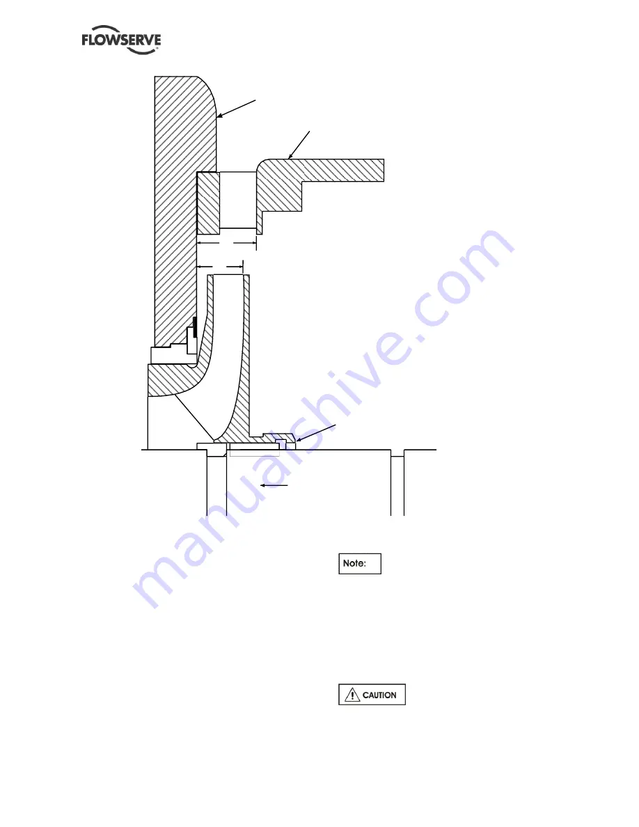
set rotor running position (See ROTOR AXIAL
A
B
Discharge Diffuser
Discharge Spacer
Discharge Impeller
1. Measure distance A on discharge diffuser
2. Push rotor inboard until it stops.
3. Measure distance B.
4. Obtain dimension of shroud position (X)
from Operating Specifications.
5. Perform calculation:
If impeller flow passage is wider than
D = (A - B) + X
If diffuser flow passage is wider than
impeller flow passage (as in a pump):
diffuser flow passage (as in a HPRT):
D = (A - B) - X
6. Record lateral movement (D). It is required to
Inboard
ALIGNMENT below).
Figure 6- 8 : Rotor Lateral Movement
6.9.2 Casing Cover
The casing cover [1221] fits closely with a clearance
of 0.03 to 0.10 mm (0.001 to 0.004 in.) between the
casing cover [1221] and bore of the casing [1100].
Hence, you must take care to pull the casing cover
[1221] straight out of the casing [1100] after
breaking it loose with jack screws; conversely, the
casing cover [1221] must be pushed straight into the
casing [1100].
6.9.2.1 Assembling Casing Cover
Proceed with the assembly of the casing cover
[1221] as follows:
For guidance in tack welding replacement
parts, contact your nearest Flowserve Sales Office
(see section 6.2.1).
1) Cool balance drum bushing [1600] in dry ice to
shrink it enough to slide it into casing cover.
Secure bushing with method employed originally
by the factory, see step 2 under disassembling
casing cover (section 6.7.7.2).
Failure to use Inner head expansion
gaskets [4590.2] and spacers [3645] that are of the
same thickness, diameter, material, quality, and
quantity as those supplied originally with the pump
could result in improper makeup of diffusers, the
suction spacer casing [1130], and the discharge


