


Valve Disassembly
a
WARNING:
To carry out this operation, it is essential to disconnect
the valve from the pipework. Depressurize line to atmospheric pressure
and drain all fluids before working on the valve. Failure to do so can
cause serious injury. Remove the valve from the pipeline.
Refer to Figure 4 to find parts according to the item numbers.
13.1
Remove the actuator from the body by separating the actuator
at the yoke. Refer to the installation, operation and maintenance
manual for the corresponding actuator.
13.2
Remove the four bonnet nuts (item 114).
13.3
Remove the packing nuts and gland flange (item 80).
13.4
Carefully pull the shaft (item 51) out of the body. The bonnet,
thrust bearing, packing stop and packing will all slide out of the
body bore as an assembly.
NOTE:
At this point in the disassembly operation, the plug is
inside the valve body and is only supported by the end post.
When removing the end post, support the plug so it does not
drop into the bottom of the valve body.
13.5
Remove the end post nuts (item 119) and carefully remove the
end post (item 122) from the body.
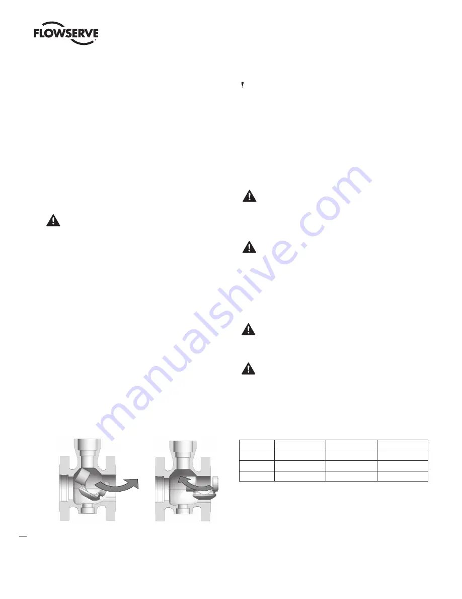
13.6
Remove the plug from the body. See Figure 5a.
13.7
Loosen the packing-box nuts (item 117) and remove the shaft
from the bonnet by sliding it out slowly. The thrust bearing
(item 46) and the shaft stop spacer (item 47, only for sizes 10
to 12”) can now be removed from the shaft.
13.8
Remove the packing follower (item 87) as well as the packing
(item 88), spacers (item 93) and the packing stop (item 99).
13.9
Remove the bonnet gasket (item 58) and end post gasket (item
61). Clean all bearing and seal surfaces.
13.10 Remove the shaft bearing (item 83) from the valve body. Use a
suitable dowel to push the bearing out if necessary. Be careful
not to damage the bearing.
13.11 Unscrew the seat retainer (item 30) using the appropriate tool
(see Table 10) and remove the seat (item 20).
Valve Reassembly
NOTE:
Lubricate all threads, bearings and the shaft shoulder with a
boron nitride paste (Molydal NB1200) or a nickel anti-seize lubricant
(Permatex 77164 or equivalent). Place the valve body in a vice and
clamp securely in a vertical position.
13.12 Always use new packing and gaskets when reassembling a valve.
13.13 Make sure that the shaft, bonnet bore and gasket surfaces in
the body have been thoroughly cleaned (these are sealing sur-
faces and it is imprtant to remove any contamination before
reassembly).
13.14 Make sure that all bearing surfaces have been cleaned.
13.15 Insert the plug in the body as shown in Figure 5b.
NOTE:
The end post bearing (item 84) is pressed into the plug.
13.16 Place the end post gasket (item 61) on the end post (item 122).
Insert the end post into the small flanged port in the end of the
body. As the end post is inserted, locate the plug (item 50) so the
end post will insert into the end post bearing located in the plug.
NOTE:
For valves 3’’ and larger, insert the end post with the
milled faces parallel to the flanges of the valve body.
13.17 Tighten the end post nuts to finger tight.
13.18 Insert the shaft bearing (item 83) into the body until the shoulder
on the bearing contacts the step in the valve body. The bearing
will protrude slightly into the body gallery area.
13.19 Place the thrust bearing onto the shaft. Slide it up to the thrust
runner. The shaft thrust bearing will surround the thrust runner.
NOTE:
for sizes 10” and 12”, an end spacer (item 47) is
placed above the thrust bearing.
13.20 Place the bonnet gasket (item 58) on the gasket step inside the
body. Gently push the bonnet into the bonnet bore.
NOTE:
When installing the bonnet, orient the milled faces on
the bonnet perpendicular to the flanges of the valve body.
13.21 Place the packing stop (item 99) into the bonnet, then install
the packing spacer (item 93) and packing set (item 88).
Figure 5a: Plug removal
Figure 5b: Plug installation
Table 9: Nut tightening torques for bonnet and post
Stud Size
A193B7
A193B8 cl2
A453Gr660 (Nace)
M8
12 ft-lb / 16 Nm
7.5 ft-lb /10 Nm
10.5 ft-lb /14 Nm
M12
43.5 ft-lb / 59 Nm
27.5 ft-lb /37 Nm
30.5 ft-lb /41 Nm
M16
62.5 ft-lb / 85 Nm
39 ft-lb /53 Nm
43.5 ft-lb /59 Nm
MaxFlo 4 Control Valve FCD VLENIM0064-02-AQ – 09/16
14


