


|
14
LM900006 Rev 0_3
Assembly of Smart-Trak™
Step
Six
SENSOR LOCATION:
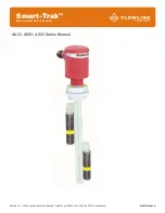
Smart Trak™ is shipped with a specific length of the track and two sensors attached. The three values at the
end of the part number are assigned to provide the length of the track (A-Dimension), the activation location of
the bottom sensor (B-Dimension) and the activation location for the top sensor (C-Dimension). See example
below.
The sensors are attached to the track via a sensor car kit. The design of Smart
Trak™ enables the end user to adjust the location of the sensor in the field for
further fine tuning of the application. Simply loosen the locking nut on the sensor
to be moved, slide the sensor along the track and then turn the nut back to lock
into place.
NOTES:
No more than a ¼ to ½ a turn to unlock and lock the nut is required.
The cable for the sensor is designed to be submersed, is made of the same
material as the sensor.
Sensors can easily be raised from their original position, but may not be
lowered because of pre-cut cable lengths.
For systems ordered with both switches positioned at the bottom of the track
(A, B and C-dimensions are all the same), it does not matter which switch is
the high and which is the low. The controller logic looks for both switches to be
either WET or DRY before the relay switches. The switches can actually be
reversed and the system will still be functional.
If needed, the excess cable may be looped outside of the track with no effect
on the systems performance.