2 4
G B
I E
CY
N I
Adjusting the chain tension
The adjustment of the chain tension is de-
scribed in the chapter: Assembly,
tension-
ing chainsaw.
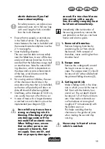
Starting up a new saw chain
In the case of a new chain, the tensioning
force decreases after some
time. Therefore,
you have to re-tension the chain after the
5
-
utes’ sawing time.
Never attach a new chain
to a worn drive pinion or
place onto a damaged or
worn chain bar. The chain
could spring back or break,
potentially leading to serious
injury.
F
Maintaining the chain bar
Use cut-protection gloves
when handling the chain or
the chain bar.
1. Switch off the saw and pull out the
power plug (12).
2. Remove the sprocket chain wheel cov-
ering (8), the saw chain (5) and the
chain bar (4).
3. Check the chain bar (4) for wear. Re-
move burrs and straighten the guide
4. Clean the oil passages (
26) of
the chain bar, in order to guarantee
a trouble-free, automatic oiling of the
saw chain during operation.
5. Mount chain bar (4), chainsaw
(5) and sprocket chain wheel covering
(8) and tighten the chainsaw.
With the oil nozzles in good condi-
tion and the oil regulator set cor-
rectly, the saw chain will spray a
little oil off after starting.
F
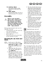
Turn the chain bar
Use cut-protection gloves
when handling the chain or
the chain bar.
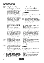
The blade (4) has to be reversed regularly
after a working time of approximately 10
hours in order to ensure even wear.
1. Switch off the saw and pull out
the power plug (
A
12).
2. Remove the sprocket chain wheel
covering (8), the saw chain
(5) and the chain bar (4).
3. Turn the blade around its hori-
zontal axis and install the blade
and chain as described under
“Installing the sawing chain and
blade”.
When doing so, pay attention to
the correct rotation direction of
the saw chain!
Direction of travel of the
saw chain
Use the graphical symbol below the chain
sprocket cover (8) as a guide to the align-
ment of the saw chain (5) when the blade
is rotated. The illustrated direction of travel
on the blade is no longer true.
Содержание FKS 2200 G4
Страница 3: ...3 C 1 2 3 5 6 17 A 14 13 15 16 7 9 7 9 11 12 19 B 2 4 10 8 3 16 20 21 22 18...
Страница 4: ...4 R N S Q P O M L K 1 2 1 2 3...
Страница 30: ...3 0 G R CY 16 180 ml A 1 2 3 4 5 6 O 17 16 15 13 14 18 9 7 8 10 12 19 20...
Страница 32: ...3 2 G R CY 7 1 Lwa dB II...
Страница 33: ...3 3 CY G R 460 mm...
Страница 34: ...3 4 G R CY A...
Страница 35: ...3 5 CY G R 30 mA H05RN F 75 2 5 mm2...
Страница 36: ...3 6 G R CY N...
Страница 37: ...3 7 CY G R...
Страница 38: ...3 8 G R CY 1 E 1 B...
Страница 39: ...3 9 CY G R 1 A A O B...
Страница 40: ...4 0 G R CY FI 30 mA A 1 10 3 5 17 15 13...
Страница 41: ...4 1 CY G R 11 18 1 2 7 8 3 5 4 5 4 45 5 24 5 4 5 23 23 5 6 5 9 7 8 25 8 7...
Страница 42: ...4 2 G R CY 10 9 N 1 kg 2 10 min B 1 16 2 7 3 9 9 4 7 5...
Страница 43: ...4 3 CY G R A 4 C 21 C 22 190 ml Parkside Grizzly 6 8 C 1 2 2...
Страница 44: ...4 4 G R CY D 1 2 3 3 16 4 1 16 5 14 13 14 6 13 E 1 2 3 3 16 4 1 16 5 6 3 3 16 7...
Страница 45: ...4 5 CY G R 26 F 1 2 3 7 9 8 4 4 5 4 45 5 24 5...
Страница 46: ...4 6 G R CY 2 15 18 cm...
Страница 47: ...4 7 CY G R 1 2 1 45 2 3 A 1 3 45 4 B 5 cm 1 10...
Страница 48: ...4 8 G R CY 5 6 7...
Страница 49: ...4 9 CY G R 1 2 3 2 1 3 3 1 3 4 1 2 3...
Страница 50: ...5 0 G R CY A 8 A 4 26 10 24 A 5 A 5 A 4 A 4...
Страница 51: ...5 1 CY G R 10 G 30 85 0 65 mm...
Страница 52: ...5 2 G R CY H 1 2 3 4 0 mm 4 5 6 4 mm 7 8 0 65 mm 5 10 F 1 12 2 8 5 4 3 A 4...
Страница 53: ...5 3 CY G R 4 26 5 4 5 8 F 4 10 1 A 12 2 8 5 4 3 5 8...
Страница 55: ...5 5 CY G R A 13 ser vice ser vice ser vice A 5 A 5 A 5 service...
Страница 56: ...5 6 G R CY 3 291822...
Страница 89: ...2017 11 23_rev02_sh informativ informative Explosionszeichnung Exploded Drawing o 22 4 8 9...
Страница 90: ...3 G F E D 14 13 24 9 23 3 3 16 16 1 16 24 9 23 F 4 5 25 8 24 7 4 5 0 45 I H 26...
Страница 91: ......

