


F
L
O
M
A
G
3
0
0
0
-
In
st
al
la
tio
n
a
nd
O
p
er
at
io
n
M
an
ua
l
3
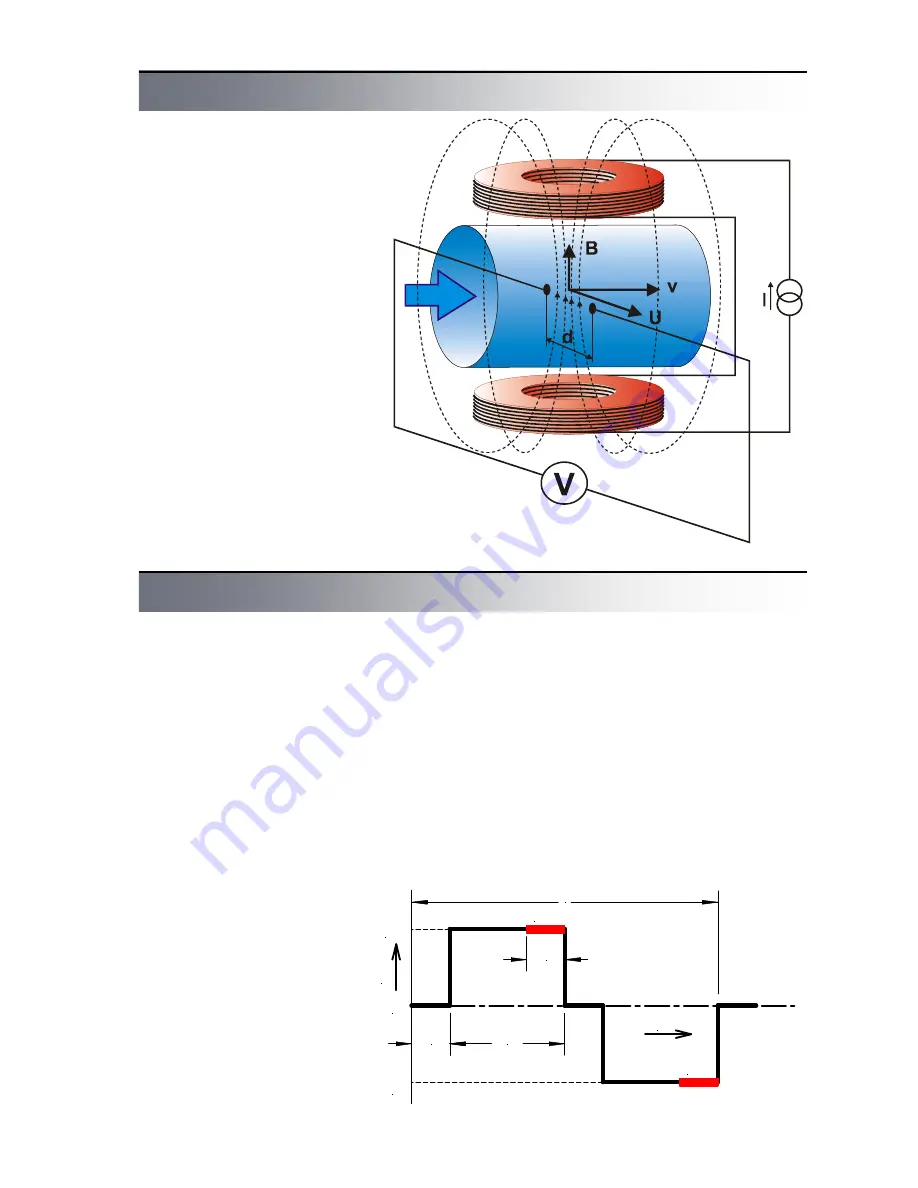
An magnetic flowmeter is used
for volume flow measurement of
electrically conductive liquids.
Measurement principle is based
on Faraday law on electromag-
netic induction. A sensor con-
sists of a non-magnetic tube
with non-conductive lining,
measuring electrodes and two
coils generating electromag-
netic field. Flowing liquid forms
a conductor. Magnetic field in-
duces voltage
U
in this conduc-
tor that is proportional to mag-
netic induction
B
, distance be-
tween electrodes
d
and flow
velocity
v
.
U = B x d x v
As magnetic induction and dis-
tance between electrodes are
constant, induced voltage is
proportional to velocity of liquid
flow in the tube. Volume flow
rate is product of flow velocity
and tube cross section.
Q = v x S
Fig.1 - Principle of measurement
Principle of measurement
Technical solution
The magnetic flowmeter itself
consists of two basic parts – a
flow sensor and a converter.
The converter can be either an
integral part of the sensor
(compact version) or separated,
connected with the sensor us-
ing a cable (remote version).
The sensor consists of a non-
magnetic tube with non-
conductive lining, measuring
electrodes, excitation coils and
cables. There are various sen-
sor versions available enabling
connection to adjacent tubes
with flanges (type
P
) and fittings
(gas fitting type
G
or food indus-
try fitting type
V
) or wafer which
are installed between flanges
using clamps (type
B
). Non-
conductive lining can be made
of technical rubber (types
TG
,
MG
or
NG
) or Teflon (type
T
).
The converter is used for gener-
ating excitation current in coils,
processing of signal from meas-
uring electrodes, displaying of
measured data and generating
output signals. Current in exci-
tation coils has constant value
250 mA or 125 mA and is pulse
generated with alternating po-
larity to avoid permanent mag-
netization of the sensor. Excita-
tion pulse frequency can be
chosen from six values – 25 Hz,
12,5 Hz, 8,33 Hz, 6,25 Hz,
3,125 Hz and 1,56 Hz. Excita-
tion current of 250 mA with ex-
citation frequency 3,125 Hz is
suitable for all standard applica-
tions. Other settings can be
used for specific applications.
Excitation current and fre-
quency are factory set before
sensor calibration and their later
modifications are not allowed.
Voltage induced in measuring
electrodes is measured always
on the end of excitation pulse
when magnetic field is steady.
Each excitation pulse is fol-
lowed by refreshing period. Sig-
nal processing and parameter
setting are performed digitally
and the converter contains no
setting controls or other moving
parts what ensures its high reli-
ability and long-term stability.
T
t
I
+I
-I
m
m
1/8T
3/8T
1/8T
0
Fig. 2 - Excitation pulse form


