Flomag 3000 Скачать руководство пользователя страница 12

F

L

O

M

A

G

 3

0

0

In

st

al

la

tio

a

nd

 O

p

er

at

io

M

an

ua

12 

Parameter setting


The  magnetic  flowmeter  con-

verter  can  be  configured  in  two 
ways,  as  required:  either  using 
a PC connected via serial inter-
face, or using keys. 

Press 

4

 to switch the display 

to  programming  mode.  Pro-
gramming  mode  is  password 
protected  against  unauthorized 
access.  Correct  password  (4-
digit  number)  must  be  entered 
to obtain access to main menu. 
Password  of  a  new  instrument 
is always set to 0000. 
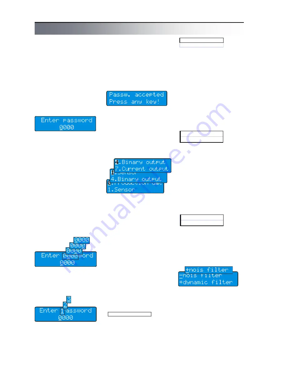
Fig. Enter password 

This  is  also  initial  value  dis-

played  as  default.  Simply  con-
firm it to enter in menu. 

Password can be changed as 

required  before  you  leave  the 
programming mode. 

Warning!  You  can  switch  the 

instrument to data display mode 
anytime  by  pressing 

1

  and 

check  current  parameter  set-
tings.  However,  the  instrument 
is  not  password  protected 
against  unauthorized  access 
until  you  enter  EXIT  command. 
Programming  runs  in  back-
ground  and  with  only  a  few  ex-
ceptions  has  no  influence  to 
measurement. 

Fig. Cursor movement 

2

  key  moves  cursor  to  the 

right.  When  the  utmost  right 
position  is  reached,  the  cursor 
returns to the left. 

Fig. Character changing 

system returns to the first avail-
able character. 
Character  set  is  always  se-
lected  with  regard  to  possibility 
of  character  occurrence  in  text: 
[0..9]  for  integers,  [0..9,-  ,  .]  for 
decimals  and  complete  alpha-
bet  for  text  variables  (including 
Czech characters). 

Confirm  your  selection  by 

4


key to finish editing. 

A status message will  be  dis-

played.  If  your  password  is  not 
accepted,  program  returns  to 
editing  mode.  If  correct  pass-
word  was  entered,  you  will  get 
to main menu. 

Use 

3

 to move in menu. This 

key moves the lower line item to 
upper  line.  In  all  menus,  the 
upper  line  with  blinking  first 
character  is  always  the  active 
line.  

Press 

4

 to  enter in submenu 

or  to  edit  item. Pressing    

in  submenu  brings  you  always 
back  to  previous  menu 
(“Escape” function). If you are in 
main menu, pressing of this key 
will offer exit from programming 
mode. 

Menu legend 

Some  menu  items  can  be 

used  only  for  viewing  and  do 
not allow change of values. 

Fig. Movement in menu 

Fig. Status message 

+ Noise f ilter
+ Dynamic f ilter

»  En te r  p a s s w o r d

 125 mA

 250 mA

¤  Pr o d u c tio n  d a te

3

  key  changes  character  at 

cursor  position.  When  the  last 
available  character  is  reached, 

Fig. Read only 

Fig. Enter value 

Press 

 to return to previous 

menu. 

Other  menu  items  can  be 

used to enter value directly. 

When you enter the value and 

press 

4

, a status message will 

be displayed. 

If  the  value  entered  is  ac-

cepted,  press any key to return 
to previous menu or to edit next 
item. 

If  the  value  entered  is  out  of 

range, an error message will be 
displayed; press any key to edit 
the value. 

In  some  cases,  one  of  listed 

values has to be selected. 

Fig. Selection of one value 

Use 

3

 to select required item. 

When  the  required  value  is  in 
the upper line, press 

4

 to con-

firm  your  selection.  A  status 
message  will  be  displayed  to 
confirm  that  your  selection  has 
been  accepted.  Press  any  key 
to return to previous menu or to 
edit next item. 

In  some  cases,  more  of  listed 

values can be selected. 

Fig. Selection of more items 

There  is  a  sign  “+”  (indicating 

that  the  item  is  selected)  or  “-
“ (indicating that the item is not 
selected) before each of items. 

Fig. Selection of more items 

Press 

2

  to  change  selection 

for  the  item  displayed  in  the 
upper  line.  Press 

4

  to  finish 

your  selection.  A  status  mes-
sage  will  be  displayed  to  con-
firm  that  your  selection  has 
been  accepted.  Press  any  key 
to return to previous menu.   

Содержание 3000

Страница 1: ...FLOMAG s r o V Aleji 180 20a CZ 620 00 Brno Czech Republic tel 420 541212539 fax 420 549240356 e mail info flomag com www flomag com Magnetic Flowmeter FLOMAG 3000 Installation and Operation ...

Страница 2: ...FLOMAG 3000 Installation and Operation Manual 2 ...

Страница 3: ...le enabling connection to adjacent tubes with flanges type P and fittings gas fitting type G or food indus try fitting type V or wafer which are installed between flanges using clamps type B Non conductive lining can be made of technical rubber types TG MG or NG or Teflon type T The converter is used for gener ating excitation current in coils processing of signal from meas uring electrodes displa...

Страница 4: ...r pump For the same reason never locate stop valves behind the sensor Fig 7 Stop valves The sensor can work both in horizontal and vertical positions only axis of measuring elec trodes inside the sensor must always remain in horizontal po sition and tapping of the sensor should be directed upwards at horizontal installations Fig 8 Electrode axis For vertical installations liquid should flow upward...

Страница 5: ...ure and MG with soft structure Soft structure is used for fluids with higher content of abrasive parti cles e g sand It is not suit able for drinking water Resistant rubber Type NG is suitable for me dium aggressive fluids with op erational temperatures from 0 1 C to 90 C It can be used for measurement of hot service water condensate etc as well as for drinking water If tem perature 100 C can be e...

Страница 6: ... 2 0 D N 2 5 D N 3 2 D N 4 0 D N 5 0 D N 6 5 D N 8 0 D N 1 0 0 D N 1 2 5 D N 1 5 0 D N 1 5 D N 2 0 0 D N 2 5 0 D N 3 0 0 D N 3 5 0 D N 4 0 0 D N 5 0 0 D N 6 0 0 D N 7 0 0 D N 8 0 0 D N 9 0 0 D N 1 0 0 0 D N 1 2 0 0 2 3 4 5 10 10 2 3 4 5 10 2 3 4 5 10 2 3 4 5 10 2 3 4 5 10 2 3 4 5 10 1 3 4 2 3 4 5 l s m h 3 2 Tab Sensor ranges in m3 h according to their sizes Fig Limit of maximum relative error of ...

Страница 7: ...tively they can serve for indica tion of flowmeter limit condi tions Galvanic isolation is en sured by an optoelement or a relay One position module 7 is dedicated for the active ana log output module Modules with various accuracy and ranges are available One posi tion module 6 is designed for the serial communication mod ule RS 232 RS 485 or M Bus interface can be plugged in Position module 2 is ...

Страница 8: ...sor with the remote converter If the instrument is used in environ ment with strong electromag netic interference cables should be rather as short as possible For connection of electronic converter input and output ter minals shielded cables are suit able For connection of mains volt age a standard three core ca ble e g CYKY 3x1 5 wire or VM03VQ F 3x1 wire strand is recommended The instrument has ...

Страница 9: ...art of measurement Total volume Total volume of liquid flowed in opposite direction of arrow on the sensor from start of meas urement Volume difference Difference between positive and negative volumes flowed from start of measurement Operation time Total time of operation from initial switching instrument on in hours and minutes Percent flow rate Flow rate information indicated by horizontal bar i...

Страница 10: ...sh key 4 Fig Hour archive Fig Daily archive Fig Month archive Fig Legend Fig Hour archive moving Fig Daily archive moving Fig Month archive moving Ok without power off s power off time in secunds m power off time in minutes h power off time in hours d power off time in days Error messages Fig Error messages In case of a fault an error message with short de scription of the fault is shown immediate...

Страница 11: ... the cables or too long ca bles E13 Sensor signal over range Signal from the sensor is overrange of the convertor electrodes are not sub merged or there is short cir cuit of the cables check the sensor and the cables User outputs plug in modules T0 5A 250V position 8 position 1 position 2 position 3 position 4 position 5 position 6 position 7 Flowmeter converter in basic configuration contains the...

Страница 12: ... line item to upper line In all menus the upper line with blinking first character is always the active line Press 4 to enter in submenu or to edit item Pressing 2 in submenu brings you always back to previous menu Escape function If you are in main menu pressing of this key will offer exit from programming mode Menu legend Some menu items can be used only for viewing and do not allow change of va...

Страница 13: ...itation curr 125 mA 250 mA Supressed flow Do not meas Q Samples Samples Filters Noise filter Dynamic filter Zero setting Autozero PIN 2 Module 2 Specific settings for individual modules 7 Module 7 Specific settings for individual modules 8 Display Language CZ Česky D Deutsch GB English PL Polski I Italiano NL Nederlands S Svenska E Espanol F Francais 100 per cent 100 per cent Flow rate units l s m...

Страница 14: ...nterference is not in cluded in cumulated vol ume It can however cause delay of flow rate jump change indication This fact should be considered if the flowmeter is used for dosing applications Response to unit jump can be seen in figure 8 Display This submenu relates to data shown on the display Language language of displayed data You can select from 9 languages 100 per cent 100 flow rate for bar ...

Страница 15: ...max 0 Qmax Qmax 0 Qmax Qmax 0 Qmax Qmax 0 Qmax 0 Q output 0 0 20 4 4 20 0 0 10 0 0 5 0 Q output 20 0 0 20 4 4 10 0 0 5 0 0 0 IQI output 20 0 20 20 4 20 10 0 10 5 0 5 Q Q output 0 10 20 4 12 20 0 5 10 0 2 5 5 0 20mA A1 Range 0 4 20 mA Resolution 12 bit Accuracy 0 2 0 2mA Active replaced by A5 A2 Range 0 4 20 mA Resolution 16 bit Accuracy 0 1 0 1mA Active replaced by A5 A3 Range 4 20 mA Resolution 1...

Страница 16: ...y are generated immedi ately If the preset volume flows through sooner than the previ ous pulse is finished the unsent pulse will be stored in a buffer with maximum capacity of 255 pulses If buffer overflow oc curs an error message will be generated It follows from above mentioned that parameters of pulse output should be set such that expected pulse frequency cannot exceed limit frequency determi...

Страница 17: ...y open Perm Closed IQI pulses Pulse length 10ms IQI not pulses Pause length 10ms Q pulses Vol pulse ml Q not pulses Q pulses Q not pulses Q frequency Flow rate at 1 kHz Q frequency IQI frequency Fixed frequency Fixed frequency Hz Negative flow Non neg flow Error occured E1 No error occured E13 Q Qlim Flow limit Q Qlim not Hysteresis Q Qlim Q Qlim not IQI Qlim IQI Qlim not IQI Qlim IQI Qlim not Cle...

Страница 18: ...ble with total length of 1200 meters Number of stations and length of cables can be increased by using re peaters Stations are connected to the link in parallel The most distant ends of line have to be equipped with terminating resis tors 120 Ω When setting stations be sure to set the same baud rate for all of them and to set a unique address for each of them MASTER address is al ways set to 0 and...

Страница 19: ...rmed periodi F1 Electrochemical elec trode cleaning module F2 Empty pipe detection module F3 Module with combined functions F1 F2 cally The cleaning cycle takes 1 minute During cleaning no real measurement is performed Flow rate measured before start of cleaning is simulated Clean ing cycle duration can be indi cated using binary outputs Running cleaning process is indicated on display by moving f...

Страница 20: ...for manual batch control Phase 0 Stop During phase 0 outputs are inactive no batching runs wait ing for start of the batching process Manual start is real ized by holding button 3 and simultaneous pushing of button 4 or from outside with the help of module E in Batch Start mode During that phase the batch volume is set To enter edit mode it is necessary to hold button 2 and simultane ously push bu...

Страница 21: ...top According to the ability to fore cast exactly the advance the batch can slightly overflow which means to go to phase 0 or the batch will not finish and will go to phase 3 In this case it is possible to go to phase 0 by choosing Reset or from outside with the help of module E in Batch Stop mode In the same time takes place presetting of the volume batch accroding to the preset value Second poss...

Страница 22: ... 162 280 250 215 96 16 125 5 16 245 192 310 250 305 126 21 150 6 16 280 218 340 300 305 126 28 200 8 16 335 274 398 350 380 211 35 250 10 10 405 370 480 450 380 211 42 5 300 12 10 440 420 535 500 515 320 55 350 14 10 500 480 584 550 515 320 65 400 16 10 565 530 642 600 515 320 94 450 18 10 565 530 642 600 515 320 94 500 20 10 670 640 752 600 515 320 122 600 24 10 780 760 870 600 615 320 158 700 28...

Страница 23: ...h tolerance 0 2 mm Weight of the sensor without converter and terminal box weight of terminal box has to be added for remote version 0 25 kg weight of converter has to be added for compact version 0 9 kg The sensor is designed for installation between flanges and for fastening by clamps not included in delivery For sensor sizes DN20 DN120 flanges with corresponding dimensions are used For sensor s...

Страница 24: ...of terminal box has to be added for remote version 0 25 kg weight of converter has to be added for compact version 0 9 kg The sensor is connected to the pipeline using an aseptic screwed fitting that meets DIN 11 851 stan dard Part of the fitting with cap nut is firmly fixed to the sensor Welded counterpart with male thread and sealing are part of delivery This sensor version is suitable for foods...

Страница 25: ...be are equipped with male tube thread Adjacent tubes have to be equipped with fitting with cap nut not included in delivery and sealed using gasket not included in delivery Protection compact version IP66 remote version IP67 optionally IP68 Electrodes Ss stainless steel AISI316Ti Ha Hastelloy C22 Ti Titanium Pt platinum Lining TG hard rubber MG soft rubber NG resistant rubber PTFE Teflon Pressure ...

Страница 26: ...rodes Pt platinum electrodes TG hard rubber lining MG soft rubber lining NG resistant rubber lining PTFE Teflon lining 6 10 16 25 40 nominal pressure bars 150lb 300lb nominal pressure lb 10 1200 nominal bore diameter mm 3 8 50 nominal bore diameter inches PDIN flanged version flanges according to DIN PANSI flanged version flanges according to ANSI B wafer version V version with aseptic fittings fo...

Страница 27: ... fitted A7 pasive output module 4 20 mA 16 bit B1 binary output passive optoMOS 250V AD DC max 120mA max 4kHz B2 binary output passive optoMOS 60V AD DC max 300mA max 10kHz B3 binary output active 5 VDC max 10mA max 12kHz B4 binary output active 24 VDC max 40mA max 12kHz B5 binary output relay 250VAC 1A module not fitted M1 memory module for data archiving module not fitted F1 electrochemical elec...

Страница 28: ...FLOMAG 3000 Installation and Operation Manual 28 ...

Отзывы: