www.flockaudio.com [email protected] [email protected] @flockaudio
Hardware Setup Menu
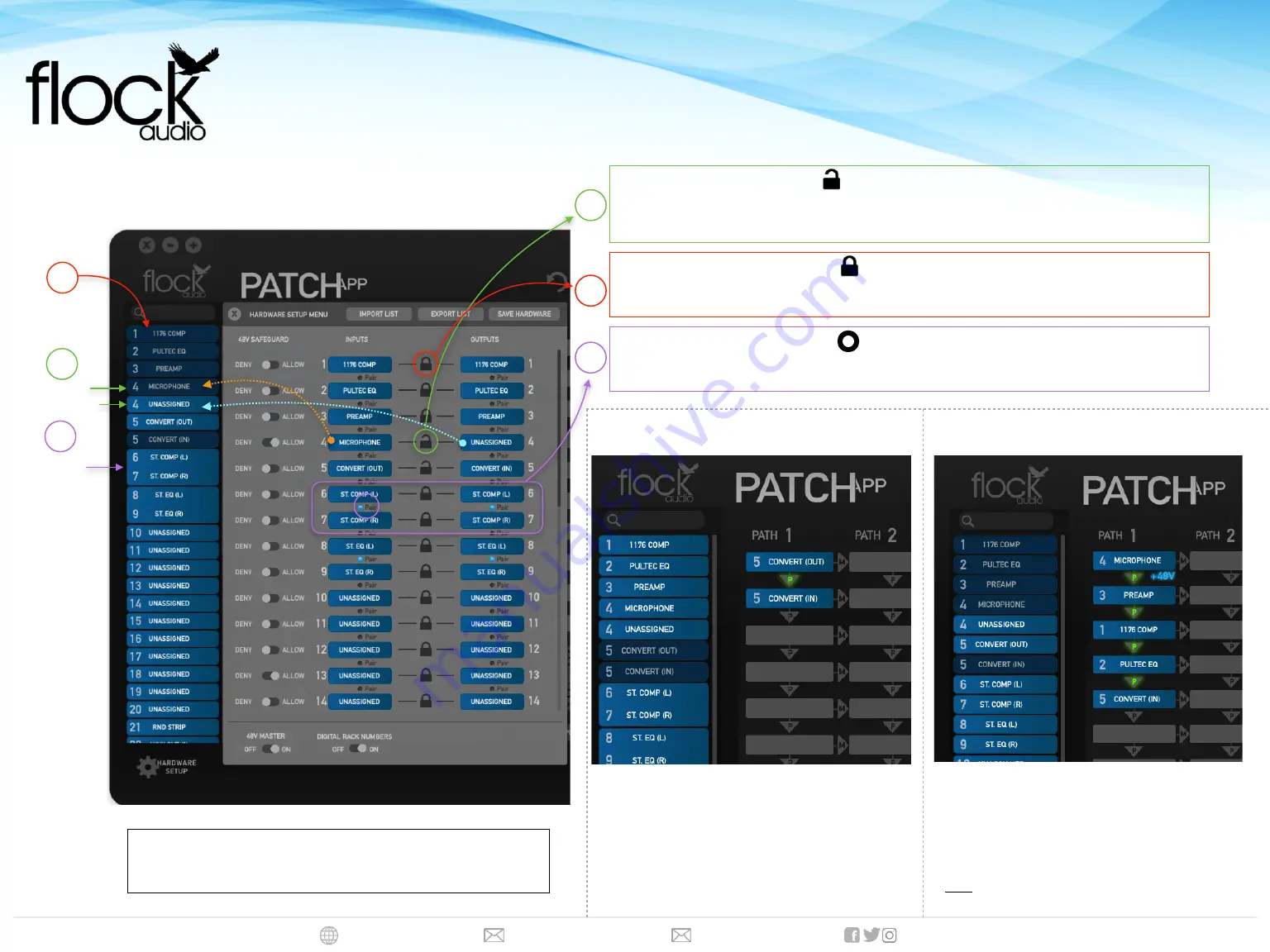
Hardware Setup Menu Labelling should show as above in-order to
properly allow your PATCH System to route audio signal flows.
Unlinking/Unlocking
Unlinking Digital Rack Spaces allows the Inputs & Outputs to be separately routed for additional flexibility.
Note
: When Unlinking Digital Rack Spaces, there will be (2) Digital Rack Spaces populated in the Hardware Index. The
Top
will be the
PATCH (
Input
)
and the
Bottom
will be the
PATCH (
Output
)
PATCH
(Output)
A
A
Linked/Locked
Linked Digital Rack Spaces will allow the I
nputs & Outputs
to be routed with only
1
Single Digital Rack
Space Representing both the Input & Output when routing in the Active Routing Grid.
B
Converter Output to Converter Input Routing
This example shows a simple Converter (Output) to
Converter (Input) PATCH APP Routing. This routing will
allow a user to send audio Out from their Converter
(DAW) and back In to their Converter (DAW)
Microphone to Converter Input Routing w/
Additional Signal Processing
This example shows a Microphone with Additional
Processing between the Audio Signal Source and the
Converter (DAW).
NOTE:
Externally connected Preamp 48V Phantom Power cannot be passed
through the PATCH System Series.
Example Routing
#1
B
SETTING UP YOUR PATCH MODEL FOR THE FIRST TIME
QUICK SETUP DIAGRAM
Stereo Pairing
Stereo Pairing can be achieved by selecting the “Pair” Icon any multiple corresponding Input and Output
Channels. More about “Stereo Paring” can be found in the PATCH Series User Manual.
C
SETUP & LABELLING DIAGRAM
PATCH
(Input)
PATCH
(Input)
&
(Output)
Linked/Combined
C
PATCH
Stereo Pairs
Example Routing
#2


