FLIR FC-Series S Скачать руководство пользователя страница 15

427-0073-12-12 Version 120

May 2015

1-11

1

Camera Installation

1.6.8

Camera Grounding

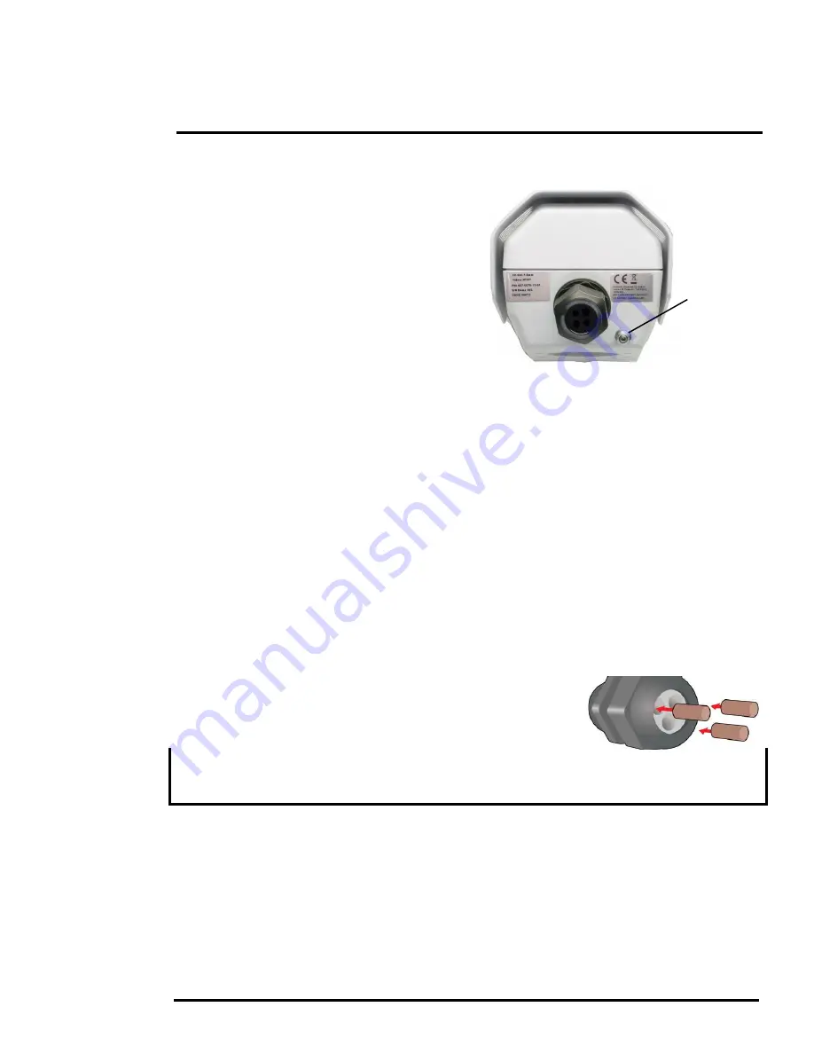
Ensure the camera is properly grounded. Failure to 
properly ground the camera can lead to permanent 
damage to the camera. Typical to good grounding 
practices, the camera chassis ground should be 
connected to the lowest resistance path possible. 
The camera has an external ground connection on 
the outside back of the camera. FLIR requires a 
grounding strap anchored to the grounding lug and 
connected to the nearest earth-grounding point. 

If, during installation, any ground connections 
inside the camera are disconnected, they should 
be reconnected prior to closing the camera. 

1.7

Rear Access Cable Gland Sealing

Proper installation of cable sealing gland and use of appropriate elastomer inserts is critical to long 
term reliability. Cables enter the rear of the camera mount enclosure through a liquid-tight 
compression gland. 

Leave the gland nut loosened until all cable installation has been completed, and ensure the 
manufacturer’s recommended cable bend radius is observed within the enclosure. Do not forget to 
tighten the cable gland seal nut to ensure a watertight seal and provide strain relief for cables. 

Cable Gland Seal Inserts

The FC-Series camera comes with a single 3/4” NPT cable gland installed in the camera, with a four-
hole gland seal insert. The gland includes a sealing washer and is secured to the camera with a nut 
on the inside of the enclosure. The gland insert has one hole for the RG-59/U analog video cable (the 
larger hole) and three more for a power cable, Ethernet cable, and an accessory cable (not used at 
this time). 

Any of the holes which are not used for cables should be filled with one 
of the hole plugs (supplied). Install the cables through the cable gland 
so that the cables line up with the connections inside the camera. 

Note

To ensure a water tight seal when using the supplied rear cable gland, cable dimensions must be 
within the minimum and maximum as described in Table 1-4.

If non-standard cable diameters are used, an appropriate cable gland and insert should be used to fit 
the desired cable and to fit the hole in the enclosure. FLIR Systems, Inc. does not provide cable gland 
inserts other than the insert supplied with the system. 

If a replacement is used, inspect and install the gland fitting in the back cover with suitable leak seal or 
sealant and tighten to ensure water tight fittings. To fit the 1.050 in. (26.7 mm) hole in the enclosure, 
the thread size should be 3/4” NPT or M25. The gland should be installed with a sealing washer (for 
example, Heyco PN 3261 or equivalent) between the gland and the external surface of the enclosure.

Insert the cables through the cable glands on the enclosure before terminating and connecting them. 
In general, terminated connectors will not fit through the cable gland. If a terminated cable is required, 
it is possible to make a clean and singular cut in the gland seal to install the cable into the gland seal.

Figure 1-15: Camera Ground Connection

Ground

Содержание FC-Series S

Страница 1: ...Installation Manual FC Series FC Series S FC Series R...

Страница 2: ...he receiving antenna Increase the separation between the equipment and receiver Connect the equipment into an outlet on a circuit different from that of the receiver and or Consult the dealer or an ex...

Страница 3: ...ng Drilling Holes 1 7 1 6 2 Configuring the Lens Heater Jumper 1 8 1 6 3 Bench Testing 1 8 1 6 4 Analog Video Connections 1 8 1 6 5 Connecting Power 1 9 1 6 6 Ethernet 1 9 1 6 7 GPIO Connections 1 10...

Страница 4: ...e Setup 3 2 IR page 3 2 3 1 2 Video Analytics Setup 3 4 Analytics page 3 4 3 1 3 Setting Analytics Properties 3 7 3 1 4 Temperature Monitoring Setup FC Series R camera only 3 10 Radiometry Page 3 10 3...

Страница 5: ...FC Series camera system always follow the warnings and cautions in this manual when handling and operating the camera 1 1 Warnings and Cautions Warning Caution 1 2 References FLIR Doc 427 00XX XX 19S...

Страница 6: ...tallations using PoE power and IP video only a single Ethernet cable from the camera is required In installations using analog video and conventional power 24 Vac is commonly used in many installation...

Страница 7: ...onents Fixed Camera Unit with sunshield and installed cable gland Cable gland plug and gland inserts for sealing camera housing Power terminal block plug Accessory terminal block plug Tools 3 mm hex w...

Страница 8: ...can be used with the bottom mount fasteners also Refer to the FC Series ICD for additional information If using two 1 4 20 fasteners in the center of base the maximum depth of the fastener should not...

Страница 9: ...al cable bend radius is 50 75mm 2 3 in 1 4 2 Camera Mounting with Concealed Cable Wall Mount The FC Series camera can be secured to the optional Concealed Cable Wall Mount with four M5 x 0 8 threaded...

Страница 10: ...a is held in place with four 3 mm hex screws The screws are accessible through slots in the sunshield so the sunshield does not need to be removed from the top cover Use a 3 mm hex key to loosen the f...

Страница 11: ...cable routing requirements and route the cables before installing the components Use cables that have sufficient dimensions to ensure safety for power cables and adequate signal strength for video an...

Страница 12: ...onnect the power Ethernet and video and confirm that the video can be displayed on a monitor when the power is turned on For configuration and basic setup information using the onboard web server refe...

Страница 13: ...d re tighten the screw terminals The camera itself does not have an on off switch Generally the FC Series camera may be connected to a circuit breaker and the circuit breaker will be used to apply or...

Страница 14: ...when an external voltage is supplied to these pins When open the resistance between pins 2 and 3 is greater than 100 K ohm When closed the resistance between pins 2 and 3 is less than 200 ohm The maxi...

Страница 15: ...ra with a nut on the inside of the enclosure The gland insert has one hole for the RG 59 U analog video cable the larger hole and three more for a power cable Ethernet cable and an accessory cable not...

Страница 16: ...through the gland Ensure the manufacturer s recommended cable bend radius is not exceeded within the enclosure Prepare the Camera Step 1 Use a 3 mm hex key to loosen the four captive screws and remov...

Страница 17: ...M5 x 0 8 threaded fasteners to the bottom of the camera Use Loctite 222 low strength thread locker for the mount fasteners Step 6 As needed clean the o ring and the o ring groove in the bottom of the...

Страница 18: ...ace the cover and tighten the four 3 mm hex screws to 1 8 n m 16 0 in lbs Caution Step 12 Using the hex key that is included with the concealed cable mount loosen the ball joint on the bottom of the m...

Страница 19: ...ield Of View Focal Length for available FC Series R camera lens configurations FC 334 R 34 28 13 mm FC 324 R 24 19 19 mm FC 645 R 45 37 13 mm FC 632 R 32 26 19 mm Spectral Range 7 5 to 13 5 m Lens Ath...

Страница 20: ...IP66 IP67 Operating temperature range 50 C to 70 C 58 F to 158 F continuous 40 C to 70 C 40 F to 158 F cold start Storage Temperature range 55 C to 85 C 67 F to 185 F Humidity 0 95 relative Shock IEC...

Страница 21: ...pport can only provide limited support in this regard 2 1 IP Camera ONVIF Profile S Compliant The FC Series camera is an IP camera with a microprocessor inside that runs the camera firmware When the c...

Страница 22: ...a conventional power supply there are several ways to bench test the camera It is recommended that the installer test the camera using the same type of connections as in the final installation Even if...

Страница 23: ...er to Basic Camera Configuration pg 2 10 Open a web browser and enter http 192 168 250 116 The login screen with a picture of the camera will appear A pull down list in the upper right allows the user...

Страница 24: ...b browser only and does not affect the video streams to other users or to an NVR For slow communication links if there is a problem displaying the video image it may help to slow down the frame rate H...

Страница 25: ...light may turn off temporarily while waiting for the response from the camera After a short pause the Control light should turn green Observe what happens to the image when the Zoom In control is clic...

Страница 26: ...s and contrast to adjust Depending on the time of day weather and other conditions one Scene Preset may be preferable to the others Function The FC Series cameras have additional features or functions...

Страница 27: ...ontrol a camera and stream video from the camera For more detailed information on how to use FSM refer to the FLIR Sensors Manager User Manual Once the software is installed the manual is available fr...

Страница 28: ...lient server architecture The FSM software is considered a client and the cameras are considered servers or sensors The Sensors Panel in the upper left of the window indicates no sensors have been dis...

Страница 29: ...ontrols in the Control Panel For example click on the zoom button magnifying glass with and the video will zoom in To test the GPIO input and output connectors click on the triangle to the left of the...

Страница 30: ...mage problems including a complete loss of video Additional information is provided in Thermal Image Setup pg 3 2 When a user logs in as admin a complete Maintenance menu is available refer to Global...

Страница 31: ...tarted Once the IP address of the camera is changed the PC may no longer be on the same network and therefore may not be able to access the camera until the IP address on the PC is changed also For th...

Страница 32: ...ver or can be entered manually If NTP mode is selected the NTP server information can be entered The Nexus server must be stopped before changes can be saved After saving changes it is necessary to re...

Страница 33: ...ateway and DNS servers are configured in the LAN Settings refer to LAN Settings pg 2 11 Configure the Msg Systems page with mail server information and then click Save Notification Lists Use this page...

Страница 34: ...s active and running and another configuration that is saved and possibly different than the running configuration The message at the bottom of the page indicates the saved configuration is different...

Страница 35: ...ddresses are entered select the Save button to save the changes To maintain security of the system set new passwords for each of the three login accounts requires the admin login user The user account...

Страница 36: ...ects energy that is directly radiated from objects in the scene Most objects in typical surroundings are not hot enough to radiate visible light but they easily radiate the type of infrared energy tha...

Страница 37: ...arts on an engines and exhaust pipes appear white while the sky puddles of water and other cold objects appear dark or cool 4 Scenes with familiar objects will be easy to interpret with some experienc...

Страница 38: ...play If the connectors appear to be properly connected but the camera still does not produce an image ensure that power has been properly applied to the camera and the circuit breaker is set properly...

Страница 39: ...o communicate on the network Select the check boxes domain private public that are appropriate for the network the By default the camera will broadcast a discovery packet two times per second When FSM...

Страница 40: ...is icon indicates the camera has been discovered and added to the list of active servers but the camera is not actively connected to FSM and therefore FSM is not receiving status updates To connect to...

Страница 41: ...indows Personal Firewall may ask for permission to allow the FLIR Video Player vp exe to communicate on the network Select the check boxes domain private public that are appropriate for the network If...

Страница 42: ...to varying conditions automatically The installer should keep in mind that the sky is quite cold and can strongly affect the overall image It may be possible to avoid a problem by slightly moving the...

Страница 43: ...very time needed 2 7 Setting the IP address on a Windows PC To set the computer IP address in Windows first connect the PC to a switch or connect it to the camera and ensure the camera has power Step...

Страница 44: ...shown at the right Step 3 Select Internet Protocol Version 4 TCP IPv4 as shown Then click Properties Step 4 Select Use the following IP address then enter 192 168 250 xxx where xxx is any number betw...

Страница 45: ...kup of the existing configuration file prior to making changes and another backup once the changes are finalized If necessary the camera can be restored to its original factory configuration or one of...

Страница 46: ...e the entire page to refresh including the image and all the parameter values be patient this may take some time To make adjustments to the thermal image it is possible to modify the Automatic Gain Co...

Страница 47: ...button from the Live Video page control panel Digital Detail Enhancement DDE DDE is an image processing technique that enhances details by emphasizing lines and edges Flat Field Correction FFC The FFC...

Страница 48: ...to set up areas or regions for detection In some situations it may also be useful to use multiple detection regions up to four to include or exclude different areas in the scene and to set area speci...

Страница 49: ...the Detection Box parameter to Yes to display different color bounding boxes on the image that indicate the status of the analytics the Save button at the bottom has to be clicked before any boxes are...

Страница 50: ...ate a human alarm The Tolerance percentage determines how closely the sizes of the moving box and the calculated box must match A tolerance of 10 will effectively cause the maximum bounding box to inc...

Страница 51: ...ter the Human Size settings are satisfactory return to this section and set the Vehicle Size parameters To set the Human Size properties have a person walk around at the bottom of the area and adjust...

Страница 52: ...p on page 3 4 However there are some differences with how the areas are created and with how the near and far parameters are set In FSM the analytics areas are configured using the Advanced Sensors Co...

Страница 53: ...ht and width parameters remains consistent with the defaults When the Human Size Near Height or Width is clicked on a convenient simulation of a human or vehicle will appear on the image at the top or...

Страница 54: ...all measurements or each measurement can have its own set of correction factors Radiometry Page Using FSM or the web Setup menu Radiometry page it is possible to create up to four areas spot or box f...

Страница 55: ...ment spot or box including Alarm conditions are configured in the Properties box to the right of the page and described below refer to Measurement Item Properties The measurement data will appear on t...

Страница 56: ...e Alarm Threshold is the temperature set point that will trigger the alarm when the Alarm Condition is met The value is in degrees Celsius or Fahrenheit depending on the camera setting refer to IR pg...

Страница 57: ...see a summary of all the defined Radiometery Measurement Items The Alarm Id is referenced by the Alarm Manager when configuring an alarm response rule refer to Alarm Manager pg 3 23 Using FSM for Rad...

Страница 58: ...ccessible including Sensor Files and Product Info 3 2 1 Sensor Menu Most of the configuration changes that are more commonly used are done through the Sensor menu including configuration steps from th...

Страница 59: ...from a web browser Refer to Security Options pg 2 15 to add an allowed IP address to the list in the Restrict Web Configuration section VMS Remote If the camera is used with a third party VMS that is...

Страница 60: ...tments to the IR settings should only be made by someone who has expertise with thermal cameras and a thorough understanding of how the various settings affect the image Haphazard changes can lead to...

Страница 61: ...Input for the input signal and IO 1 Output for the output signal Then the label can be displayed in FSM or another VMS client on the network Click on the Save button to save any changed settings The c...

Страница 62: ...ters However in some cases such as when a video stream is sent over a wireless network it may be useful to tune the video stream to try to reduce the bandwidth requirements In particular the RTP Setti...

Страница 63: ...parameter is set to yes an alternate IP address can be entered Note always use an even port number for the RTP Port parameter By default the video streams from the camera are sent using unicast packet...

Страница 64: ...dwidth and possibly lower quality An Instantaneous Decoder Refresh IDR frame is a special type of I frame and the first image in a stream is always an IDR image Frames sent after IDR can be decoded wi...

Страница 65: ...a only The Label can display the Friendly Name configured on the Product Info page the Hostname configured on the LAN Settings page or a Custom text string using the Text parameter after selecting Cus...

Страница 66: ...h as the IP address and Serial Number By default this information is displayed on the video overlay analog and IP for 10 seconds The Thermography Info setting controls whether the Thermography OSD tem...

Страница 67: ...ground sensor fence system or other security sensor Alarm Source The source of alarms for the FC Series S camera is typically internal from Video Analytics and or GPIO Input while the FC Series R cam...

Страница 68: ...ification when it is sent To attach a snapshot select an option from the Attach Image File pull down list The option All Non Radiometric sends a normal JPEG image and Radiometric sends a radiometric J...

Страница 69: ...t ID set to 0 which corresponds with the input IO 0 refer to GPIO pg 3 17 then takes a snapshot and stores it in the Media Browser pg 3 27 The Action is set to Capture Image File and that causes a sna...

Страница 70: ...e to view the Nexus Configuration File perform Backup Recovery of local files on the camera and perform Upload Download of configuration files to another computer for backup or to install a new config...

Страница 71: ...e image In this case IR0 is the only sensor Select Download to download the selected file the PC Select Refresh to check for any additional images since landing on the Media Browser page Select Edit t...

Страница 72: ...the Config File page are described below Use the Config File page to change the Friendly Name which appears in FSM by default You can also include the Friendly Name on the video feeds and adjust its a...

Страница 73: ...ra has a custom loopback connector installed on its Ethernet interface The detection of the loopback packet cues the camera to restore Factory Defaults including the IP settings user passwords and con...

Страница 74: ...Inc 70 Castilian Drive Goleta CA 93117 USA PH 1 805 964 9797 PH 1 877 773 3547 Sales PH 1 888 747 3547 Support FX 1 805 685 2711 www flir com Corporate Headquarters FLIR Systems Inc 27700 SW Parkway A...

Отзывы: