background image

FT-13 Technical Manual, Rev. 1.40   March 2013


Page 38 of 56  

8.3.2 Setup 

There are several setup parameters for the Ethernet network as described below: 

Host Name 

Device name on the network. Default is “ “ 

IP Address 

The numeric code that identifies all computers that are connected to the internet. 
Default is “92.168.16.250” 

Local Port 

Ethernet connection point of the device. Default is “10001” 

Gateway 

Network point that acts as an entrance to other networks. Default is “192.168.16.254” 

Subnet Mask 

Defines a range of IP addresses in a network. Default is “255.255.255.0” 

Primary DNS 

Primary DNS server IP address 

Secondary DNS 

Secondary DNS server IP address 

DHCP 

The Dynamic Host Configuration Protocol provides dynamically allocated IP 
addresses to computers on a network, if it is enabled. 

Remote Connect. 

Automatic connection to any device on the network 

Remote IP 

IP address of the PC or device which should be connected automatically 

Remote Port 

Ethernet connection point of the device which should be connected automatically 


Important hint:

 During the setup the Ethernet output (weight value and status bits) will not be updated. 

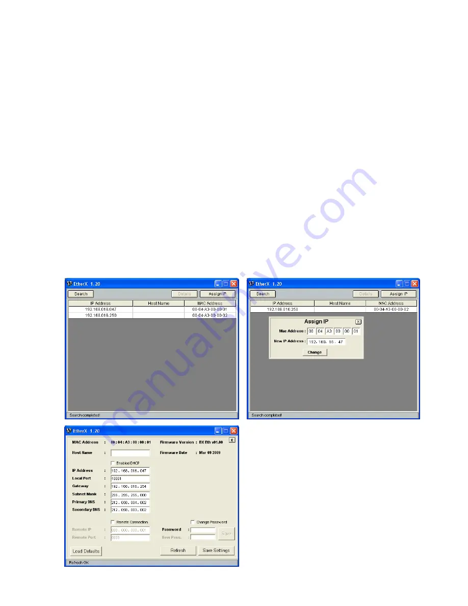
Setup by using the Ether X Software: 

Note: 

For older instruments the configuration will be done by the Ethernet Device Installer PC 
software, see separate document on the Flintec Product-CD. 

 
Step 1: 

Install the Ether X software from the Flintec Product-CD to any PC on the network 

Step 2: 

Start the Ether X software 

Step 3: 

After pressing the “Search” button the software lists the FT-1x devices on the network as shown in 
the figure below 

Step 4: 

The IP address of any device may be changed after clicking the “Assign IP” button 

Step 5: 

Click the “Details“ button to open the parameter window as shown below. 


The parameter window presents information like 
Firmware Version of Ethernet option board and it helps 
to edit resources like Host Name, Gateway, DNS 
server etc. 
 
After changing any parameter, enter the password and 
click the “Save Settings” button. 
The default 

Password is “123456”. 

 
The “Load Defaults” button resets the device to the 
default settings. 

Содержание FT-13

Страница 1: ...WEIGHING CONTROLLER FT 13 T TE EC CH HN NI IC CA AL L M MA AN NU UA AL L For Firmware Version 2 13 and higher Flintec GmbH Bemannsbruch 9 74909 Meckesheim GERMANY www flintec com...

Страница 2: ...n 14 6 1 Basics 14 6 1 1 Basic Setup Keys on the Frontplate 14 6 1 2 Entering the Setup and Calibration Menu 14 6 1 3 Exiting the Setup and Calibration Menu 14 6 2 Metrological Counter 14 6 3 Configur...

Страница 3: ...etup 38 8 3 3 Data Structure 39 8 4 Profibus Option 40 8 4 1 Electrical Connections 40 8 5 2 Setup 40 8 5 3 Data Structure 40 8 6 ProfiNet Option 41 8 6 1 Electrical Connections 41 8 6 2 Setup 41 8 6...

Страница 4: ...not be liable against any damages or problems arising from the use of any options or any consumable products other than those designated as Original FLINTEC Products NOTICE The contents of this manua...

Страница 5: ...FT 13 Technical Manual Rev 1 40 March 2013 Page 5 of 56 2 DECLARATION OF CONFORMITY...

Страница 6: ...000 intervals in single range scales 90 384 EC directive AND for 6 000 intervals in single range scales 2004 22 EC directive Approved sensitivity of 0 4 V e according 90 384 EC directive and 0 83 V e...

Страница 7: ...ustment Only externally Digital filter 10 step adjustable Filling programmes Open container filling Below bunghole filling Below surface filling Filling and emptying 2 types Filling and discharging Ch...

Страница 8: ...0 15 70 100 15 Stainless steel housing front view Stainless steel housing side view 100 mm deep with big backplane option 3 4 2 Panel Type Housing Panel type front view Panel type side view 9 5 5 69 1...

Страница 9: ...unding FT 13 is available with 230 V AC power supply or 24 V DC or 12 V DC power inlet The 230 V AC indicators are supplied with a power cable the DC indicators are supplied with a special connector f...

Страница 10: ...4 digital inputs and 8 digital outputs The meanings of the various I O depend on the selected standard filling programme see chapter 7 Definition Pin no P Pin no SS Programme J10 J15 Standard JR1 JR2...

Страница 11: ...o the instrument 4 3 Commissioning After making the required installations and connections to your indicator turn the power on and perform following steps Get familiar with the instrument s setup mode...

Страница 12: ...ive W Mod Weighing mode is active G N Gross Net LED is on when gross is displayed temporarely Stable The weight value on the display is stable Center of zero The weight is in the center of zero see pa...

Страница 13: ...and Q keys sequentially The message Qty is displayed Enter the quantity you want to fill and press Enter Total This key is used to display the total filled weight and the batch report To view the tota...

Страница 14: ...n by pressing the Enter key As you enter the block you will reach the first sub block in that main block The sub block address will be seen on the display as X0 You can also search between the sub blo...

Страница 15: ...r 141 Time HH MM First press a key for the time entry then enter the new date via numerical keys and save by pressing Enter 6 4 Scale Parameters 2 Scale Block The parameters related to the weighing op...

Страница 16: ...later the display will show the SAvE message You can confirm the Save zero adjustment by pressing Enter or cancel it by pressing the F key 311 Span Adjustment This parameter lets you perform the span...

Страница 17: ...ng programme 2 Prepare the digital I O connections according to the selected filling programme see chapter 4 2 3 3 Set up and calibrate the scale see chapter 6 4 Enter the process parameters for the s...

Страница 18: ...0 s to 9 9 s The delay parameter may be helpful for some special processes tArE is the minimum tare value The filling can start if the weight of the container is higher than this value It can be enter...

Страница 19: ...art delay This period can be entered by keypad from 0 0 s to 9 9 s The delay parameter may be helpful for some special processes tArE is the minimum tare value The filling can start if the tare of the...

Страница 20: ...ds after removing the container from the scale Process Parameters Description When FT 13 is in Ready status the top LED in the LED bar is on press the keys shown on the left sequentially d_F LL means...

Страница 21: ...tion This message is displayed during the start delay It disappears at the end of the start delay Means the filling valve is going down It disappears when the filling valve is completely down Means th...

Страница 22: ...pad up to 25 0 s Emptying type If it is set to 1 the weight is followed during emptying When the weight goes into the zero range the d_d SC delay starts and the gate is closed at the end of this delay...

Страница 23: ...and 180kg can be discharged sequentially Process Parameters Description When type FT 13 is in the Ready status the top LED in the LED bar is on press the keys shown on the left sequentially This is t...

Страница 24: ...ing must be sequential Process Parameters Description When type FT 13 is in the Ready status the top LED in the LED bar is on press the keys shown on the left sequentially The period for the dSChrG me...

Страница 25: ...gate is opened and emtying starts When the weight goes into the zero range d_d SC delay starts and the gate is closed at the end of this period The delay time can be entered by the keypad up to 9 9 s...

Страница 26: ...r catching the system as shown in the figures above The process cycle starts with the start input in the ready status The close the clamp output will be set and then the filling is start if the clamp...

Страница 27: ...played during the automatic zeroing cycle after the cycle start if applicable This message is displayed at the end of the Filling for d_End delay time 7 3 9 Programme 8 Bag filling from hopper scale O...

Страница 28: ...ut is hold for this time period It can be entered up to 25 0 seconds The clamp release delay time is used to open the clamp at the end of the vibration process It can be entered up to 25 0 seconds Emp...

Страница 29: ...alue To edit the value use the numeric keys and press the Enter key Coarse lead in Target Coarse cut off see figure 7 1 The mid feed lead in value is shown on the display if 3 speed feeding is enabled...

Страница 30: ...ric keys and press Enter To hide a recipe enter 0 tolerance of filling or discharging are shown To edit the value use the numeric keys and press Enter The coarse lead in value is shown on the display...

Страница 31: ...cycles X 0 1 2 3 9 factory default setting is 1 Attention This parameter must be set to 1 if all cycles have to be controlled for tolerances If you don t want to make preact correction but data loggi...

Страница 32: ...eeding are enabled sequentially 50d XX Fine feeding time at cycle start This parameter defines the fine feeding time before the coarse feeding If this parameter is set to 0 the filling operation start...

Страница 33: ...y to the weight value The error is acknowledged by the start input Valid for programme 0 1 2 3 4 5 6 7 and 8 It shows the filling period is extended The filling valves are closed The error is acknowle...

Страница 34: ...dard RS232C of the instrument should be made as given in the table below Definition Panel type housing Pin no D Sub 9 pin male Stainless steel housing Pin no J11 connector RS232C typical PC allocation...

Страница 35: ...ighing mode Example 10 01 2007 10 57 Cn 169 G 1999kg T 0kg N 1999kg DATE TIM E CN G RO SS TARE NET M S D L S D S P M S D L S D S P M S D L S D S P M S D L S D S P M S D L S D S P M S D L S D L F C R 1...

Страница 36: ...ou can access the parameters of the instruments s serial interface s in parameter section 0 The data output modes see chapter 8 3 can be used only once except for continuous data output 00 Serial Inte...

Страница 37: ...a serial interface 0 no 1 yes 8 3 Ethernet Option FT 1x series indicators which are equipped with an Ethernet option can be connected to Ethernet TCP IP or Modbus RTU over Ethernet networks as describ...

Страница 38: ...mote Port Ethernet connection point of the device which should be connected automatically Important hint During the setup the Ethernet output weight value and status bits will not be updated Setup by...

Страница 39: ...Example HyperTerminal 1 Open the HyperTerminal and choose a name for the connection Press OK 2 Then enter the Ethernet address of the indicator and the port number as shown at the left Also you need...

Страница 40: ...Green On line data exchange Flashing Green On line clear Flashing Red 1 flash Setup error Not supported Flashing Red 2 flash PROFIBUS configuration error Check GSD file Status LED State Meaning Off N...

Страница 41: ...communication present NS Network Status LED LED State Description Comment Off Not online No power Check power and cable Green On line RUN Green flashing On line STOP 8 6 2 Setup 0 Interface Block 03 P...

Страница 42: ...n in progress Red Exception error Check EDS file Error LED State Indication Action Comment Off No error No power or CANopen module is inizializing Red single flash Warning limit reached Bus error coun...

Страница 43: ...e logical condition of that output which can be changed by pressing the Zero key 904 mV Indication When pressing the Enter key the output voltage of the load cell will be shown on the display This unc...

Страница 44: ...AX WEIGHT Editable with any password Editable with any password Editable with service password Editable with service password Editable with service password and calibration jumper Editable with servic...

Страница 45: ...Bit 5 Bit 6 Bit 7 0 1 2 Decimal point 3 4 Increment size Always 1 Always 1 X 0 0 0 XXXXOO 1 0 X 1 1 0 0 XXXXXO 0 1 X 2 0 1 0 XXXXXX 1 1 X 5 1 1 0 XXXXX X 0 0 1 XXXX XX 1 0 1 XXX XXX 0 1 1 XX XXXX 1 1...

Страница 46: ...0C 00 02 Current tolerance weight Coarse 40 015 03 00 0E 00 02 Current coarse value Fine 40 017 03 00 10 00 02 Current fine value CN 40 019 03 00 12 00 01 Current consecutive Number Last filling value...

Страница 47: ...Total weight for next cycle Outputs 40 026 10 00 19 00 02 04 XX XX XX XX hex To set outputs manually Active output no Data bit no set to 1 e g only Bit 1 8 1 only output 1 8 active Middle 40 028 10 00...

Страница 48: ...00 21 F2 D1 Loading Target Tolerance Coarse and Fine in one message with above values 01 10 00 0A 00 08 10 00 00 13 88 00 00 00 32 00 00 01 F4 00 00 00 64 8F B2 Details of an example Loading value 50...

Страница 49: ...ADC over 011 ADC under 100 System error 101 FT not in weighing mode or filling mode 14 13 12 5 Not used Always 0 4 Command accepted This bit is toggled when a new command was accepted 3 Net 0 Gross M...

Страница 50: ...rom 0 to 1 activates the zero command 6 New command A transition from 0 to 1 activates the command described in the table below 5 Command Command R W Definition 00000 R Gross Weight continuous 00001 R...

Страница 51: ...tal output 2 16 Digital output 1 15 0 Not used Always 0 15 13 Error 000 No error 001 ADC out 010 ADC over 011 ADC under 100 System error 101 FT 13 not in weighing mode or filling mode 12 5 Not used Al...

Страница 52: ...0 deactivates the Hold function 13 12 Not used Always 0 11 Reset A transition from 0 to 1 activates the reset command 10 Start A transition from 0 to 1 activates the start command 9 Clear A transitio...

Страница 53: ...e the zeroing delay parameter 50F Increase the range of the motion detector parameter 206 Err 1 ADC error Re energize indicator Contact FLINTEC Err 2 Err 3 Indicator cannot get calibrated Check load c...

Страница 54: ...d 212Capacity 2 d 2 6 kg 0 001 kg 3 Calibration Adjustment 30 Calibration 301Calibration 31 Adjustment 310Zero adjustment 311Span adjustment 312Span adjustment under load Parameter Factory defaults 5...

Страница 55: ...FT 13 Technical Manual Rev 1 40 March 2013 Page 55 of 56...

Страница 56: ...FT 13 Technical Manual Rev 1 40 March 2013 Page 56 of 56 www flintec com...

Отзывы: