A.2
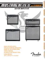
KEY FUNCTIONS
Manual DAS 72.1
Page 3
T
T
T
Inp.2
0
T
Inp.1
-
S
IGNAL
SHIELD
-
EXCIT
A
TION
-
SENSE
+
EXCIT
A
TION
+
SENSE
+SIGNAL
Load cell
connections
Power supply
12-25 V DC
+ 0
Input 1
(Functions as
Zero button,
Tare off, Set zero,
see paragraph B.3.6)
Net mode LED
Zero Key
Sets new zero (if enabled). Reverts to calibrated zero
if the button is held down for more than 3 seconds.
Switches unit back to ‘Gross’ mode if a tare has been
set. Acts as the ‘Enter’ key in the ‘Set-up’ Mode.
Tare Key
Puts unit into ‘Net’ mode. When inside
‘Set-up’ Menu this key moves the menu
back one step. Also moves ‘Digit Selected’
to the right inside sub menus.
“Set up”
menu structure
Press either key for
more than 3 seconds
to enter the set up mode
Recessed Enable Switch
(Enables changes to be made to important parameters.
Must be pressed before attempting to change
parameters 1.1 to 1.3, 2.1 to 2.3 and 3.1 to 3.3)
RS422/485
COM port
No motion LED
Logic
outputs
Logic
inputs
Input 2
(Functions as
Tare button,
Display net mode,
see paragraph B.3.6)
Down key
Up key
0 4-20mA
analogue
output
/
+ 0
Receive
+
Receive
-
T
ransmit
+
T
ransmit
-
Ground
Logic
Input
1
(+)
Logic
Input
2
(+)
Logic
Input
3
(+)
Commmon
0
Net
Digital Amp Setpoint
DAS 72.1
+ +
+
+
+
+ +
0-20mA
-
-
-
-
-
0
0
Exc Sen Sig Sig Sen Exc
Rx Rx Tx Tx
Load cell 5Vdc
80mA
Isolated
Logic Outputs
Isolated
Logic Inputs
Isolated
Power 11 -25Vdc
RS422/485
CL out
SET UP
1.Zero
1.0/allow>0<
2.Calibrate
3.Set mV/V
2.Span
1.Set cal. ´n´
2.Calibrate
3.Set mV/V
4.Disp.mV/V
3.Display
1.o/u limits´n´
2.Step * ´n´
3.Dec.point
4.Logic stats
4.Filter
1.f
Hz
2.Algorithm
3.Update rate
4.
cut
Motion´n´
5.CLout
1.4mA=´n´
2.20mA=´n´
3.Base
4.Test I mA
6.Input 1/2/3
1.Assign key
2.
3.
4.Test
7.Outp. 1/2/3
1.SPoint ´n´
2.Hyst. ´n´
3.Base
4.Test
±
8.Datacom.
1.Baud rate
2.422/485
3.Address
4.Auto trnsm.
T
T
T
0
T
Inp.1
Inp.2
1
2
3
4
5
6
7
8
9 10 11 12 13
14
27
26
15 16 17
23 24 25
18 19 20 21 22
1
2
3
com
1
2
3
com
Mark III
Io Gnd
Logic input 1
2
3
1
2
3
Logic output
Depress
To
Change