background image

- 6 -

2 Installation instruction

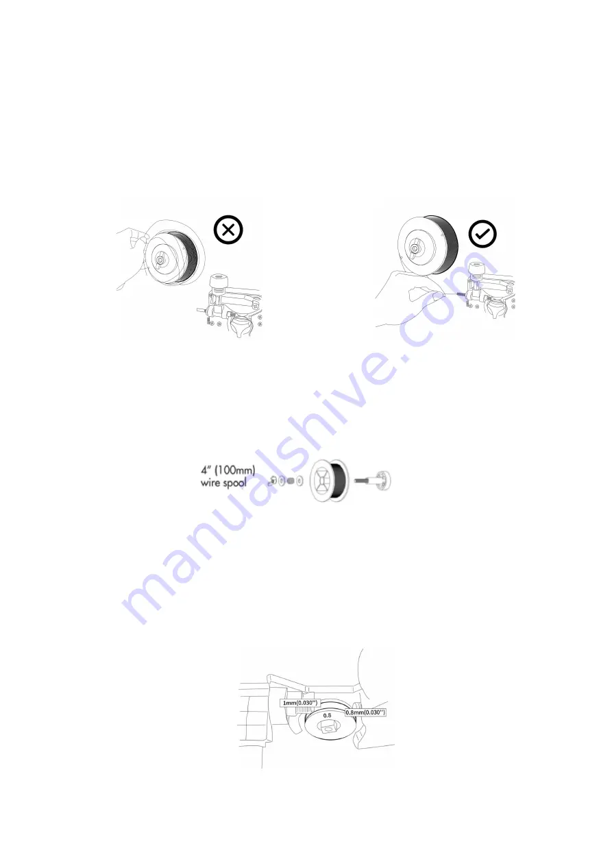
2.1 Welding wire Installation steps:

The wire holder filled with wire installed on the wire feeder. The hole position of the wire plate

should be aligned with the fixed plug on the shaft.

The wire coil should be rotated and loosen the wire, to prevent the wire from loosening, the

new wire disk head is usually inserted into the fixed hole at the edge of the wire. In normal
use, to prevent the bending of the wire to be stuck, please cut this part of wire.

0.030”(0.8mm)/0.040”(1.0mm)diameter

4”(100mm 1kg)wire spool

According to the diameter of the wire, choose different wire feed roller.V roller for stainless

steel and carbon steel. Knurled roller for flux cored wire. Please match diameter notes on the
roller with the welding wire diameter.

Roller size: external diameter

25mm/ internal diameter

7mm/ height 7.5mm

Содержание FM 155E

Страница 1: ...1 Operation Manual FM155E MIG Welding Machine...

Страница 2: ...ntents 2 1 Product brief introduction 3 1 1 Summarize 3 1 2 Technical parameters 4 1 3 Accessories list 5 2 Installation instruction 6 2 1 Welding wire Installation steps 6 2 2 MIG Torch explosive cha...

Страница 3: ...ith power supply voltage compensation device The power supply voltage can continue to work when the rated voltage is within 15 range When using longer cables in order to reduce voltage drop use a larg...

Страница 4: ...STICK 30 100 TIG 220V 30 150 MIG 30 150 STICK 30 150 TIG Output voltage V 110V 15 5 19 MIG 21 2 24 STICK 11 2 14 TIG 220V 15 5 21 5 MIG 21 2 26 STICK 11 2 16 TIG No load voltage V 50 5 Duty cycle 80...

Страница 5: ...1 2 MIG Welding Gun Torch 1 3 Welding Electrode Holder Set 1 4 Earth Electrode Holder Set 1 5 Gas hose 1 6 Flux Cored Welding Wire 1 This equipment is mainly used in industry In the indoor environment...

Страница 6: ...disk head is usually inserted into the fixed hole at the edge of the wire In normal use to prevent the bending of the wire to be stuck please cut this part of wire 0 030 0 8mm 0 040 1 0mm diameter 4 1...

Страница 7: ...ng while feeding the wire The welding gun is inserted into the output socket of the front panel and screwed tightly And put the wire into the gun Unscrew the nozzle contact tip And feed the wire throu...

Страница 8: ...as or argon gas decompression flow meter is closely connected with the intake inlet of the machine Connect the machine rear gas fast plug and gas regulator with the gas hose in accessories LIFT TIG we...

Страница 9: ...9...

Страница 10: ...torch switch Effective only in MIG 0 8 MAG 0 8 FLUX 1 0 The welding machine only be operated with the Spool gun torch in the Spool gun torch mode The MIG torch only be used for welding in the MIG torc...

Страница 11: ...be obtained according to personal habits and workpiece differences 6 Mode switch The function is cycled between STICK LIFT TIG MIG 0 8 MAG 0 8 and FLUX 1 0 with each click 7 Current adjust function O...

Страница 12: ...lay The welding current range is 30A to maximum current 150A adjustment Operating procedures for MIG gas protection welding Welding wire Installation Refer to 3 1 Please choose wire feed roller V roll...

Страница 13: ...ding performance and suitable for your welding habits You may also adjust voltage and inductance to build a perfect welding bead and penetration flux cored wire Spool Gun torch welding This machine ca...

Страница 14: ...orch Connect the TIG torch on negative plug Connect the Earth cable on positive plug Fault display OC light When the welding load is overloaded and the output current of the machine is too large the i...

Страница 15: ...achines are excessively used such as with input voltage higher than the rated the machine might be damage Please pay close attention to the following matters a Keep good ventilation The welding machin...

Страница 16: ...ntacts with the work pieces well b Examine whether each joint has improper contact The output current fails to reach rated value The deviation of power voltage from rated value may cause that the outp...

Страница 17: ...current protection please turn off the power switch restart the machine after the abnormal indicator light winked It might be overheating protection please wait for about 2 3 minutes until the machine...

Страница 18: ...ble is cut off Connection joint loose Over heat Welding Power Operation Turn on power supply or not Phase Lacking Gas Cylinder and Gas Regulator Turn on gas supply Residual Amount of Gas in the cylind...

Страница 19: ...Break off bending fatigue Damaged by weighted drop Surface Condition of Parent material and length that wire stretches out Oil dirty rust and paint residues Too long length of wire stretched out Outpu...

Страница 20: ...ed for a long time pack the machine in original package and store in dry surroundings f Every time the wire feeder operates for 300hours grind the electrical carbon brush and clear up the armature com...

Страница 21: ...he suitable tube Partial winding and extended Reason of poor wires sending and unstable arc please change Block caused by dirt in the tube and the remains of the wire plating lay Reason of poor wire s...

Страница 22: ...ocket is firm If the power input end cable fixed If the input cable is worn out and bares the conductor In case of leakage and to ensure safety please do perform daily checking Earth cable If the eart...

Страница 23: ...njury Please read this manual carefully to avoid or minimize such harm Symbol definition This Manual contains symbols as blow please refer to their means expressed Symbol Definition Texts beginning wi...

Страница 24: ...as spouts causing accident Do not place fingers hair clothing etc near rotating parts such as cooling fans The welding wire is shot from the torch and can stab eyes face and other exposed parts of the...

Страница 25: ...losion please observe the following rules Do not place flammable materials near the welding place Do not welding near flammable gas Do not place the hot finished base material close to flammable mater...

Страница 26: ...s regulator instruction manual before use please observe the precautions Use a dedicated cylinder holder and related parts to secure the cylinder Do not leave cylinders exposed to high temperatures or...

Страница 27: ...machine level is maintained as far as possible When moving the gas shielded welding machine on the ground be sure to fix the cylinder with a belt or chain to prevent the dumping If the wire feeding m...

Страница 28: ...lose to each other and close to the ground d All the metal components of the welded assembly and its adjacent components shall be subject to safety verification e The workpiece should be kept well gro...

Страница 29: ...1 0 1 2 140 150 20 21 45 50 10 15 10 15 4 5 1 0 1 2 1 0 1 5 160 180 22 23 45 50 15 15 1 2 1 2 1 6 220 260 24 26 45 50 15 15 20 1 2 1 2 1 6 220 260 24 26 45 50 15 15 20 1 2 1 2 1 6 300 340 32 34 45 50...

Страница 30: ...0 270 380 29 35 45 50 25 20 25 12 1 2 1 6 50 400 32 36 35 40 25 20 25 High welding speed 1 0 0 8 0 9 45 140 19 20 160 10 15 1 2 0 8 0 9 45 130 150 19 20 120 10 15 1 6 1 0 1 2 45 180 22 23 120 10 15 20...

Страница 31: ...due to use of the product for other than domestic purposes or an incorrect voltage or use of improper accessories or contrary to operating instructions or to accidental damage misuse neglect or inexp...

Отзывы: