TEMPERATURE AND PRESSURE RELIEF VALVE
The factory fitted temperature and pressure relief valve, sited on top of the unvented cylinder, is a safet device to
back-up and support the thermostat(s) and thermal cut-out(s). It operates when either excess pressure or excess
temperature is sensed. When operated, hot water will be discharged so care must always be taken. The discharge is
connected to a tundish and drain.
Note: The temperature and pressure relief valve must not be removed under any circumstance. Such action
will invalidate the warranty.
DISCHARGE PIPEWORK FROM THE TEMPERATURE AND PRESSURE RELIEF VALVE
The tundish must be vertical and fitted within 300mm of the temperature and pressure relief valve and must be
located near the unvented cylinder. The tundish must also be in a position visible to the occupants, and positioned
away from electrical devices. The discharge pipe from the tundish should be metal and should terminate in a safe
place where there is no risk to persons in the vicinity of the discharge.
Refer to diagram C on page 8.
ALL INSTALLATIONS MUST CONFORM TO BUILDING REGULATIONS G3.
COMMISSIONING
Check for obvious signs of damage to the unvented cylinder and associated controls.
Do not switch the immersion heater(s) or fire the boiler until the unvented cylinder is full of water.
1. Open all outlet taps.
2. Turn on mains water supply and allow the unvented cylinder to fill.
3. Close taps in turn after having purged the system of air.
4. Check for leaks around the controls and immersion heater(s). Repeat this check again after the unit has
heated up.
5. Check that no water is passing to discharge through the temperature and pressure relief valve and the expansion
relief valve.
6. Test the operation of the temperature and pressure relief valve and the expansion relief valve by lifting/turning the
manually operated test cap and ensure that water flows through freely and safely to waste.
7. Check that the discharge pipe is plumbed so that it falls continuously and that no taps, valves or other shut-off
devices are installed in the pipe.
8. Check that all thermostats are set to 60
O
C.
9. DIRECT UNITS: Switch on immersion heater(s) and allow the unit to heat up. Check the operation of the
thermostat(s).
10. INDIRECT UNITS: Fill the indirect (primary) circuit, following the boiler instructions. Switch on the boiler, ensuring
that the programmer is to domestic hot water. Allow the unit to heat up and check the operation of the cylinder
thermostat on the motorised valve.
11. Demonstrate the operation of the unit to the occupier, including the temperature and pressure relief valve and
what to do if it operates.
12. Give this manual to the occupier to retain for future reference and make the occupier aware that periodic checks
of the equipment are essential for safety.
13. Complete the ‘Supastor Service History Book’ provided and leave with the occupier.
MAINTENANCE OF THE MAGNESIUM ANODE
The installer should check the magnesium anti-corrosion anode after two years (consult the label on the face of the
unit for correct location). If the heating element is heavily coated with scale we recommend descaling at the time of
this inspection. If the anode is still operational and is not replaced then further annual checks are required. If the
anode is replaced then it does not need re-checking for a further two years.
EXAMINE THE ANODE AND REPLACE IF THE DIAMETER IS LESS THAN 15mm.
Removal of Anode:
1. Close the mains supply service valve.
2. Open hot water taps.
3. Ensure the cylinder is empty.
4. The anode can now be removed.
5. Descale the immersion heater(s) and remove any lime deposit from the cylinder and heating element.
Replace in reverse order.
(continued overleaf)
4
9
L
N
L
N
L
N
L
N
Day Element
3kW 220/240V
Pre-wired
Pre-wired
Night Element
3kW 220/240V
Economy 7
TOP ELEMENT
BOTTOM ELEMENT
Thermal
cut-out
Thermo
stat
Thermal
cut-out
Thermo
stat
Element
Isolating
switch
Isolating
switch
Bottom Element
(Night Store)
Economy 7
controller
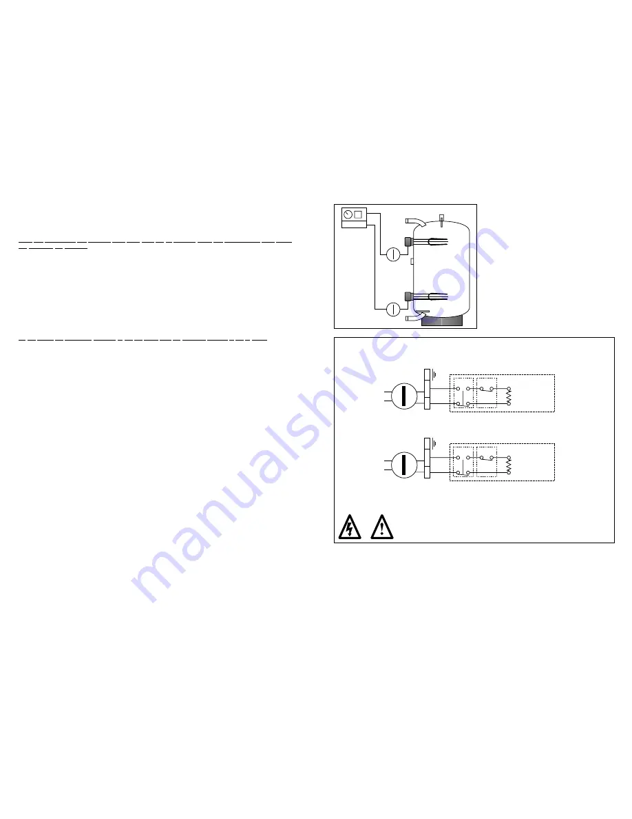
Diagram F.
Recommended Direct System
Economy 7
Recommended wiring for Supastor Direct Cylinder - Economy 7
Electrical installation must be carried out by a competent person.
Isolate unit before removing any covers.
Wire using 1.5mm
2
flexible cable, 85
O
C rubber insulated HOFR sheathed, complying with BS.6141
Table 8. It must be fully earthed and wired through a double pole isolating switch.
Diagram G.


