background image

www.Fisher.com

Fisher

r

 V150S Slurry Vee-Ball

t

 Control Valve

NPS 3 through 12

Contents

Introduction

1

. . . . . . . . . . . . . . . . . . . . . . . . . . . . . . . 

Scope of Manual

1

. . . . . . . . . . . . . . . . . . . . . . . . . . 

Specification table

2

. . . . . . . . . . . . . . . . . . . . . . . . 

Description

2

. . . . . . . . . . . . . . . . . . . . . . . . . . . . . . . 

Installation

3

. . . . . . . . . . . . . . . . . . . . . . . . . . . . . . . . . . 

Maintenance

5

. . . . . . . . . . . . . . . . . . . . . . . . . . . . . . . . 

Packing Maintenance

5

. . . . . . . . . . . . . . . . . . . . . . 

Disassembly

5

. . . . . . . . . . . . . . . . . . . . . . . . . . . . 

Assembly

6

. . . . . . . . . . . . . . . . . . . . . . . . . . . . . . . 

Actuator Mounting

7

. . . . . . . . . . . . . . . . . . . . . . . . . . . 

Determining Mounting Position

for Spline Shaft/Lever Type

8

. . . . . . . . . . . . . . . 

Determining Closed Position

8

. . . . . . . . . . . . . . . . 

Parts Ordering

9

. . . . . . . . . . . . . . . . . . . . . . . . . . . . . . 

Parts List

11

. . . . . . . . . . . . . . . . . . . . . . . . . . . . . . . . . . 

Introduction

Scope of Manual

This instruction manual provides installation,
operation, maintenance, and parts information for
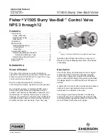
Fisher Vee-Ball V150S (NPS 3 through 12) rotary
control valves (see figure 1).

Refer to separate manuals for information
concerning the actuator, positioner and accessories.

Do not install, operate, or maintain V150S valves
without being fully trained and qualified in valve,
actuator, and accessory installation, operation, and
maintenance. To avoid personal injury or property
damage, it is important to carefully read, understand,
and follow all the contents of this manual, including
all safety cautions and warnings. If you have any

Figure 1. Fisher V150S Slurry Vee-Ball Control Valve

W8511

questions about these instructions, contact your
Emerson Process Management sales office before
proceeding.

Description

The V150S Slurry Vee-Ball valve shown in figure 1
mates with CL150 raised face flanges. Rugged
construction, highly wear-resistant trim materials,
and an unrestricted straight through flow path make
the design ideal for controlling the most abrasive of
slurries.

A shaft with a choice of drive connections will allow a
variety of power operated actuators and valve
positioners or controllers to be used.

The design is particularly effective in minimizing
erosive damage to the adjoining pipework, thereby
providing greater operational safety and service life
when compared with other valve types.

Instruction Manual

D103164X012
November 2010

V150S Slurry VeeBall Valve

Содержание V150S

Страница 1: ... avoid personal injury or property damage it is important to carefully read understand and follow all the contents of this manual including all safety cautions and warnings If you have any Figure 1 Fisher V150S Slurry Vee Ball Control Valve W8511 questions about these instructions contact your Emerson Process Management sales office before proceeding Description The V150S Slurry Vee Ball valve sho...

Страница 2: ...s Part Material Valve Body Carbon Steel ASTM A216 WCC Body Liner High Chrome Iron ASTM A532 Class III Type A V notch Ball High Chrome Iron ASTM A532 Class III Type A Flow Ring High Chrome Iron ASTM A532 Class III Type A Flow Ring Insert type optional High Chrome Iron ASTM A532 Class III Type A Flow Ring Retainer Carbon Steel ASTM A105 Bearing Shroud High Chrome Iron ASTM A532 Class III Type A Bear...

Страница 3: ...to protect against process media If installing into an existing application also refer to the WARNING at the beginning of the Maintenance section in this instruction manual Figure 3 Optional Shaft to Body Bonding Strap Assembly VALVE BODY ACTUATOR A A VIEW A A 24 E0880 CAUTION When ordered the valve configuration and construction materials were selected to meet particular pressure temperature pres...

Страница 4: ...8 18 11 81 11 97 10 63 5 19 1 50 9 25 1 81 0 69 1 Stud length associated with clearance dimension M is longer than standard length specified in ANSI B16 5 2 Clearance necessary to remove flange bolts B M N A G K D S DIAMETER U W T NPS 3 THROUGH 12 E0875 Figure 4 Fisher V150S Dimensions see table 4 Table 5 Fisher V150S Dimensions for Double D Shaft Drive VALVE SIZE E S 1 FLAT LENGTH T U W DN mm 80 ...

Страница 5: ...e taken to protect against process media Packing Maintenance 1 It is recommended that the valve be removed from the line when replacing packing to allow correct set up of the actuator after actuator removal 2 Remove the packing follower nuts and packing follower keys 18 and 16 3 Remove the packing parts see figure 4 and keys 15 and 14 using a purposed designed packing extraction tool to avoid dama...

Страница 6: ...NING at the beginning of the Maintenance section Reference figures 9 and 10 CAUTION Trim parts are made from brittle material handle with care to avoid chipping or breakage 1 Clean all surfaces of the parts to be used Ensure all mating surfaces are in good condition and free from scratches and dents Replace worn parts Fit new gaskets key 13 and 21 and packing key 15 2 Position the valve body with ...

Страница 7: ...ecommendations for assembly can be provided by your Emerson Process Management sales office Actuator Mounting Use the appropriate actuator instruction manual this section of this manual and figure 8 of this manual when mounting the actuator or changing actuator styles and positions 1 To help ensure correct centering of the V notch ball key 3 on the flow ring key 4 or 28 29 be sure the ball is clos...

Страница 8: ...l injury keep hands tools and other objects away from the ball while stroking the valve 2 Rotate the ball to the closed position 3 Position the ball in the proper location 4 The ball is in its closed position when the Vee plane of the ball opposite the convex side is parallel to the liner end flange face of the valve body Measure to check Adjust the actuator linkage or travel stops to position CAU...

Страница 9: ...pecify the complete 11 character part number from the parts kits or parts list information WARNING Use only genuine Fisher replacement parts Components that are not supplied by Emerson Process Management should not under any circumstances be used in any Fisher valve because they may void your warranty might adversely affect the performance of the valve and could cause personal injury and property ...

Страница 10: ...V150S Slurry Vee Ball Valve Instruction Manual November 2010 10 Figure 10 Fisher V150S Assembly E0879 ...

Страница 11: ...12183U012 NPS 10 2B12185U012 NPS 12 3B12213U012 Schedule 80 NPS 3 1B12085U012 NPS 4 1B12111U012 NPS 6 2B12019U012 NPS 8 2B12184U012 NPS 10 2B12186U012 NPS 12 3B12215U012 Key Description Part Number 5 Flow Ring Retainer 6 Bearing Shroud High Chrome Iron 2 req d NPS 3 1B12100U012 NPS 4 1B12100U012 NPS 6 1B12062U012 NPS 8 1B12170U012 NPS 10 1B12170U012 NPS 12 1B12201U012 7 Bearing 440C 2 req d NPS 3 ...

Страница 12: ...mirates Singapore 128461 Singapore www Fisher com The contents of this publication are presented for informational purposes only and while every effort has been made to ensure their accuracy they are not to be construed as warranties or guarantees express or implied regarding the products or services described herein or their use or applicability All sales are governed by our terms and conditions ...

Отзывы: