Fisher easy-Drive 200L Скачать руководство пользователя страница 23

Instruction Manual

D104331X012

easy-Drive 200L

December 2018

23

Appendix A - Modbus

A.1 Register Summary

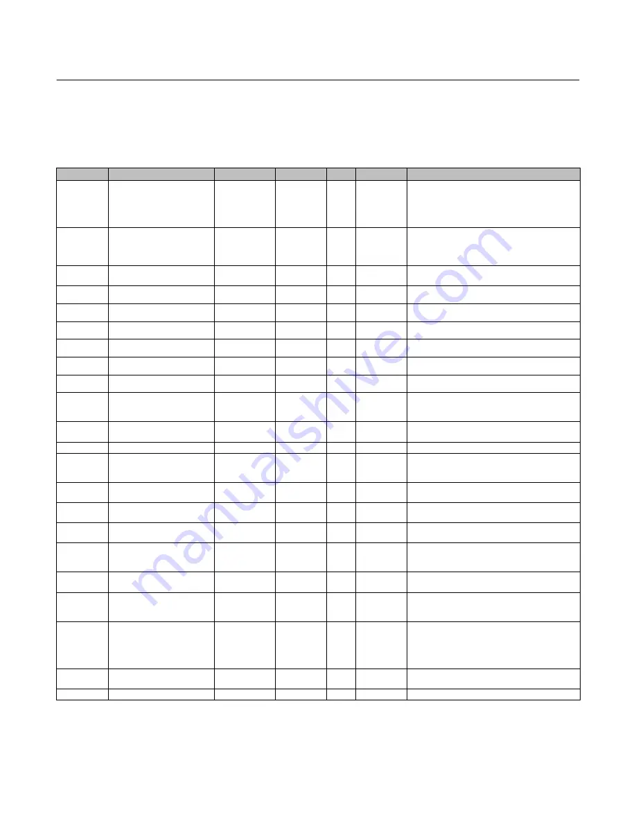
Table 3. easy-Drive 200L Modbus Map

Type

Name

MB Register

Default

R/W

Values

Notes

unit16

Modbus position command

(100=10.0%)

40001

0

R/W

0-1000

Modbus command value with one implied decimal
place (1000=100.0%). R/W at all times but only used in
Modbus control mode. In on/off mode 0-499 will
result in a move to 0% and 500-1000 will result in a
move to 100%.

unit16

Digital output

40002

0

R/W

0,1

0=no voltage supplied to terminals, 
1=voltage supplied to terminals
(Only used when output setup is set for Remote
controlled)

unit16

Reset error codes

40003

0

R/W

0,1

Value of 1 will clear faults. 
Will automatically set back to 0.

unit16

RESERVED

40004

unit16

RESERVED

40005

unit16

RESERVED

40006

unit16

RESERVED

40007

unit16

RESERVED

40008

unit16

RESERVED

40009

unit16

Actual position

(100=10.0%)

40010

0

R

0-1000

Present position of the actuator relative to span with 1
implied decimal place (1000=100.0%). Valid for all
control modes.

unit16

Commanded position

(100=10.0%)

40011

0

R

0-1000

Present position command of the actuator relative to
span (1000=100.0%). Valid for all control modes.

unit16

Diagnostic Flags

40012

0

R

0-65535

Bit flags - see chart

unit6

Digital status

40013

0

R

0 - 1

0=no connection between terminals, 
1=connection between terminals (Status of digital
input or output)

unit32

Total Running Time (min)

40014, 40015

0

R

4294967296

Total number of minutes the actuator has been
powered on since time has been reset

unit32

Total Open Time (min)

40016, 40017

0

R

4294967296

Total number of minutes the actuator has been at
100% of travel since time has been reset

unit32

Total Closed Time (min)

40018, 40019

0

R

4294967296

Total number of minutes the actuator has been at 0%
of travel since time has been reset

unit32

Number of Closed (cycle count)

40020, 40021

0

R

4294967296

Total number of close cycles the actuator has
performed since reset. 
One open/close cycle counts as 1.

unit32

Number of Power Cycles

40022, 40023

0

R

4294967296

Total number of times the actuator 
has been powered on.

unit32

Number of Movements

40024, 40025

0

R

4294967296

Total number of movements the actuator has
performed. Move must be at least 5% of rated travel
for cycle to increment.

unit16

Analog input control value

40026

0

R

0-2400

Value of the analog signal in mA with 2 implied
decimals.  In analog control mode, this is the
command value and is subject to the analog settings in
registers 40046 to 40059. Always active but a slower
refresh rate when unit is not in analog control mode.

unit16

Incoming voltage

40027

0

R

0-350

Diagnostic register - value of incoming voltage with 1
implied decimal.

unit16

Latch Open State

40028

0

R

0 - 1

Normally open latch state

-continued-

Содержание easy-Drive 200L

Страница 1: ...formation for the easy Drive 200L Do not install operate or maintain an easy Drive 200L without being fully trained and qualified in valve actuator and accessory installation operation and maintenance To avoid personal injury or property damage it is important to carefully read understand and follow all the contents of this manual including all safety cautions and warnings If you have any question...

Страница 2: ...ximum Stroke Length 19 mm 0 75 inch Maximum Thrust 3336 N m 750 lbSf Average Thrust 2446 N m 550 lbSf Nominal Stroke Speed 1 3 9 mm s 0 15 inch s at 24 VDC 2 2 mm s 0 09 inch s at 12 VDC Hazardous Area Approvals CSA C US Explosion Proof Class I Division 1 Groups C and D T6 Ex d IIA T6 Class I Zone 1 AEx d IIA T6 ATEX Flameproof Gas II 2 G Ex db IIA T6 IECEx Flameproof Gas Ex db IIA T6 Enclosure Ra...

Страница 3: ...his instruction manual WARNING For explosion proof applications ensure the actuator cover is properly bolted before applying power to the actuator Personal injury or property damage may result from fire or explosion if power is applied to the actuator with the cover removed in a hazardous area For explosion proof applications install rigid metal conduit and a conduit seal no more than 457 mm 18 in...

Страница 4: ...pment is not installed in a location where it may be subjected to external conditions such as high pressure steam which might cause a build up of electrostatic charges on non conducting surfaces Additionally cleaning of the equipment shall only be done with a damp cloth To avoid damage to the enclosure when screws are fully tightened into blind holes in enclosure walls with no washer fitted at lea...

Страница 5: ...etween the actuator and valve stems a When installing the user supplied stem connector the actuator stem s threads should engage the threads of the stem connector by a distance equal to or greater than the diameter of the actuator stem CAUTION Incomplete engagement of the actuator stem in the stem connector can result in stripped threads or improper operation Be sure that the length of each stem c...

Страница 6: ...FF POSITIONING ON OFF WIRE PER DIAGRAM FOR ON OFF WIRE PER DIAGRAM FOR 4 20 mA YES NO FIRST TIME USING Modbus CONNECT USB TO Modbus CONVERTER TO INTERNET CONNECTED COMPUTER CONNECT VIA Modbus TO VALVE AND CONFIGURED REGISTERS FOLLOW DRIVER INSTALLATION INSTRUCTIONS FOR YOUR DEVICE INSTALL easy Drive CONFIGURATION OR Modbus MASTER SOFTWARE UNIT IS READY FOR OPERATION ...

Страница 7: ...tion A 4 amp minimum power supply is required Wiring Instructions 1 Observe local wiring requirements for hazardous location usage 2 Conduit seals within 450 mm 18 inches of the enclosure port are required for explosion proof installation 3 18AWG 0 52mm2 to 12AWG 3 31mm2 wire size required 4 Fuse system to 5A 5 Connect enclosure and analog signal shields 6 Ensure power is turned off before connect...

Страница 8: ...Instruction Manual D104331X012 easy Drive 200L December 2018 8 Figure 4 Wiring Analog Input Figure 5 Wiring Dual Dry Contact ...

Страница 9: ...Instruction Manual D104331X012 easy Drive 200L December 2018 9 Figure 6 Wiring Single Dry Contact Figure 7 Wiring Modbus Input ...

Страница 10: ...Instruction Manual D104331X012 easy Drive 200L December 2018 10 Figure 8 Wiring Auxiliary Digital I O set to input 40080 0 Figure 9 Wiring Auxiliary Digital I O set to output 40080 1 10V 25 mA max ...

Страница 11: ...ation There are 2 functional configurations available for the easy Drive electric actuator On Off and Positioning All available input signals are shown in table 2 Table 2 All Available Input Signals CONFIGURATION ON OFF POSITIONING Control Source Modbus Local Modbus Local Input Signal Modbus Dual Dry Contact Single Dry Contact Modbus 4 20 mA default Modbus setup Use of a serial or USB to RS 485 de...

Страница 12: ...ngs of the actuator Default actuator settings are address 1 9600 baud even parity 1 stop bit MSB Press the AUTO button in the upper left corner to connect to the valve Use the Fisher easy Drive configuration software figure 10 to make the desired changes or register values may be changed to allow different functionality Valve Type Configuration D Valve Type H 0 5 Fixed H 0 62 Fixed H 0 75 Fixed H ...

Страница 13: ...evel When using the easy Drive Configuration Tool clicking on the Control Method box will create a drop down menu as shown Select the desired control source the selection will turn yellow A box with Pending Changes will appear showing all changes Press APPLY to confirm the change s Figure 12 Fisher easy Drive Configuration Software Calibration Instructions WARNING To avoid personal injury or prope...

Страница 14: ...hed on 4 For positioning operation using 4 20 mA a Apply a 20 mA signal between pins 4 20 mA and 4 20 mA valve plug will not move at this time b Apply a 4 mA signal between pins 4 20 mA and 4 20 mA valve plug will move to the upper stop immediately followed by moving to the lower closed position c If calibration of the analog input is desired to improve positional accuracy an optional operation is...

Страница 15: ...ged from normal to reverse acting during the calibration process 1 With the Control Method set to 4 20 Positioning or 4 20 mA Level enter the Calibration screen and the 4 20 mA Signal Calibration window will be visible 2 Click the CALIBRATE CLOSE OPEN VALUES button A separate window will open to guide through the process 3 Set the 4 20 mA signal to the desired value for when the valve is to be clo...

Страница 16: ...and open signals A differential less than that amount will cause the actuator to reject the calibration and use the previous values Should the entered values vary more than 10 from the expected 4 20 mA values the actuator will accept the calibration and a Notification displaying Questionable Analog Calibration will result Figure 16 Fisher easy Drive Configuration Software Operational Verification ...

Страница 17: ...ceed to Troubleshooting guide on page 17 5 Check conduit ports D Conduit seal must be in place within 450mm 18in of the enclosure D Unused conduit ports must be sealed with an explosion proof port plug 6 Replace the cover and tighten all 8 bolts to 20 N m 15 ft lbs Troubleshooting 1 Unit does not move a Green heartbeat LED will pulse near Modbus terminals when power is present Verify the 12VDC to ...

Страница 18: ...ess media from both sides of the valve D Back plug away from seat to relieve spring compression D Use lock out procedures to be sure that the above measures stay in effect while you work on the equipment D Check with your process or safety engineer for any additional measures that must be taken to protect against process media WARNING For explosion proof applications ensure the actuator cover is p...

Страница 19: ...ators Command the valve to anywhere between 10 and 20 travel Disconnect power and signal Proceed to step 3 For On Off Actuators Command the valve to open or close and cut the power when the valve is at mid stroke Disconnect power and signal Proceed to step 3 4 Remove actuator and mounting kit from the valve body Assembly 1 Connect actuator and mounting kit to valve body 2 Replace the top of the ex...

Страница 20: ...Instruction Manual D104331X012 easy Drive 200L December 2018 20 Figure 17 Fisher easy Drive 200L Actuator Exploded View APPLY LUB GE94736 A ...

Страница 21: ...njury and property damage Note Previous generation gearboxes may not be compatibility with the easy Drive 200L For additional information please consult your Emerson sales office Parts Kits CONTROLLER BOARD REPLACEMENT KIT POSITIONING GE83126X012 GEARBOX REPLACEMENT GE84238X022 Parts List Note For part numbers not shown contact your Emerson sales office Key Description 16 Stem 18 O ring 20 Nut Hex...

Страница 22: ...Instruction Manual D104331X012 easy Drive 200L December 2018 22 Figure 18 Fisher easy Drive 200L Actuator Assembly GE94736_ex 13 mm 13 mm 11 16 inch 1 1 2 inch 1 1 2 inch 2 inch ...

Страница 23: ... 1 0 no connection between terminals 1 connection between terminals Status of digital input or output unit32 Total Running Time min 40014 40015 0 R 4294967296 Total number of minutes the actuator has been powered on since time has been reset unit32 Total Open Time min 40016 40017 0 R 4294967296 Total number of minutes the actuator has been at 100 of travel since time has been reset unit32 Total Cl...

Страница 24: ...it16 RESERVED 40045 unit16 RESERVED 40046 unit16 RESERVED 40047 unit16 RESERVED 40048 unit16 RESERVED 40049 unit16 Loss of signal position 100 10 0 40050 0 R W 0 1001 Position to which valve plug will be driven upon loss of signal Loss of signal is based upon the active control mode 0 1000 0 100 0 with 1 implied decimal point In on off mode 0 499 will result in movement to 0 while 500 1000 will re...

Страница 25: ...100 10 0 40056 500 R W 1 1000 When the valve is in 4 20 mA on off mode this value is the point at which the valve will open It must be set to a larger value than the analog on off close position Percentage position value with one implied decimal 500 50 0 unit16 Analog Close Value 40057 40 R 31 220 The analog value in mA with one implied decimal 40 4 0 mA that defines the closed position unit16 Ana...

Страница 26: ...085 unit16 RESERVED 40086 unit16 RESERVED 40087 unit16 RESERVED 40088 unit16 RESERVED 40089 unit16 RESERVED 40090 unit16 RESERVED 40091 unit16 RESERVED 40092 unit16 RESERVED 40093 unit32 Device Tag 40094 40113 Default tag name R W 0 255 per character Device Tag 20 character UTF8 string unit32 Valve serial number 40114 40115 0 R W 0 4 294 967 296 Valve assembly serial number assigned at Fisher asse...

Страница 27: ... 294 967 296 Seconds since January 1 2000 Motor Supplier Test Date unit32 System completion date 40136 40137 0 R W 0 4 294 967 296 Seconds since January 1 2000 Final Assembly Test Date UNIT16 unsigned 16 bit variable can take value 0 65535 UNIT32 unsigned 32 bit variable can take value 0 4294967295 Reserved registers used for development use only 32bit register contains data that spans two registe...

Страница 28: ...ignal value and value entered 0x0400 0000 0100 0000 0000 Valve travel distance calibration not in legal range 1024 10 The valve travel distance is outside the acceptable range Confirm valve type and that no obstructions are present 0x0200 0000 0010 0000 0000 Analog Input span calibration not in legal range 512 9 The analog values for open and close are less than 4 mA and previous values have been ...

Страница 29: ...Instruction Manual D104331X012 easy Drive 200L December 2018 29 Appendix B Certificate of Conformance continued ...

Страница 30: ...Instruction Manual D104331X012 easy Drive 200L December 2018 30 Appendix B Certificate of Conformance cont ...

Страница 31: ...Instruction Manual D104331X012 easy Drive 200L December 2018 31 ...

Страница 32: ... are available upon request We reserve the right to modify or improve the designs or specifications of such products at any time without notice E 2018 Fisher Controls International LLC All rights reserved Fisher and easy Drive are marks owned by one of the companies in the Emerson Automation Solutions business unit of Emerson Electric Co Emerson Automation Solutions Emerson and the Emerson logo ar...

Отзывы: