Fisher DS13 Скачать руководство пользователя страница 3

FISCHER Mess- und Regeltechnik GmbH

Safety instructions | 1

BA_EN_DS13

3

1 Safety instructions

1.1 General

This operating manual contains basic instructions for the installation, operation
and maintenance of the device that must be followed without fail. It must be
read by the installer, the operator and the responsible specialist personnel be-
fore installing and commissioning the device.

This operating manual is an integral part of the product and therefore needs to
be kept close to the instrument in a place that is accessible at all times to the re-
sponsible personnel.

The following sections, in particular instructions about the assembly, commis-
sioning and maintenance, contain important information, non-observance of
which could pose a threat to humans, animals, the environment and property.

The instrument described in these operating instructions is designed and manu-
factured in line with the state of the art and good engineering practice.

1.2 Personnel Qualification

The instrument may only be installed and commissioned by specialized person-
nel familiar with the installation, commissioning and operation of this product.

Specialized personnel are persons who can assess the work they have been
assigned and recognize potential dangers by virtue of their specialized training,
their skills and experience and their knowledge of the pertinent standards.

1.3 Risks due to Non-Observance of Safety Instructions

Non-observance of these safety instructions, the intended use of the device or
the limit values given in the technical specifications can be hazardous or cause
harm to persons, the environment or the plant itself.

The supplier of the equipment will not be liable for damage claims if this should
happen.

1.4 Safety Instructions for the Operating Company and the

Operator

The safety instructions governing correct operation of the instrument must be
observed. The operating company must make them available to the installation,
maintenance, inspection and operating personnel.

Dangers arising from electrical components, energy discharged by the medium,
escaping medium and incorrect installation of the device must be eliminated.
See the information in the applicable national and international regulations.

Please observe the information about certification and approvals in the Tech-
nical Data section.

1.5 Unauthorised Modification

Modifications of or other technical alterations to the instrument by the customer
are not permitted. This also applies to replacement parts. Only the manufacturer
is authorised to make any modifications or changes.

1.6 Inadmissible Modes of Operation

The operational safety of this instrument can only be guaranteed if it is used as
intended. The instrument model must be suitable for the medium used in the
system. The limit values given in the technical data may not be exceeded.

The manufacturer is not liable for damage resulting from improper or incorrect
use.

Содержание DS13

Страница 1: ...IEC 61508 SIL2 Betriebsanleitung DS13 Differential pressure switch 09005217 BA_EN_DS13 Rev ST4 A 04 20 09005217...

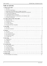
Страница 2: ...2 Product and functional description 5 2 1 Delivery scope 5 2 2 Equipment versions 5 2 3 Intended use 6 2 4 Function diagram 6 2 5 Design and mode of operation 6 3 Assembly 7 3 1 General 7 3 2 Proces...

Страница 3: ...tandards 1 3 Risks due to Non Observance of Safety Instructions Non observance of these safety instructions the intended use of the device or the limit values given in the technical specifications can...

Страница 4: ...n DANGER Type and source of danger This indicates a direct dangerous situation that could lead to death or serious injury highest danger level 1 Avoid danger by observing the valid safety regulations...

Страница 5: ...nnection Fig 2 Options for the electrical connection 2 2 3 Type plate This type plate serves as an example of the information that is stated The data shown is purely fictive but does correspond to the...

Страница 6: ...the user 2 4 Function diagram 5 6 1 1 2 3 4 Fig 4 Function diagram 1 Pressure chamber 2 Tappet 3 Micro switch 4 Switch point setting 5 Measuring diaphragm 6 Measuring springs 2 5 Design and mode of o...

Страница 7: ...e device is suitable for the medium being measured Maximum pressures must be observed cf Tech data The pressure connections are marked with and symbols on the device When the differential pressure is...

Страница 8: ...edia Settable reactor pins below the closing cap G Fig 6 Controllable damping reactor In the operational status the reactor pins need to be set so that the measure ment display follows the pressure ch...

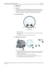
Страница 9: ...int setting Switch 1 Switch 2 Fig 8 Control elements Depending on the enclosure model the switch point setting is accessible in different ways The enclosure must be opened to set the zero point 4 3 Op...

Страница 10: ...ting Carry out the test for both mi croswitches After the test the switch points need to be reset Checking the switch points when the system is depressurized No measurement is shown and the measuremen...

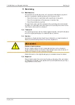
Страница 11: ...he measuring device must be protected against impacts It should be transpor ted in the original packaging or a suitable transport container 5 3 Service All defective or faulty devices should be sent d...

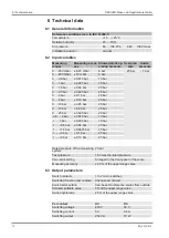
Страница 12: ...10 bar 0 25 bar 25 bar 0 16 bar 0 4 bar 25 bar 0 25 bar 0 625 bar 25 bar 0 6 0 bar 0 015 bar 10 bar 1 0 bar 0 025 bar 16 bar 1 0 6 bar 0 04 bar 25 bar 1 1 5 bar 0 0625 bar 25 bar 1 3 bar 0 1 bar 25 ba...

Страница 13: ...brass for 8 mm pipe Cutting ring connection in brass for 10 mm pipe Electrical connection Permanently wired numbered cables 7 pin plug connection Cable socket Installation position vertical Dimensions...

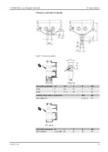
Страница 14: ...ings All dimensions in mm unless otherwise stated The following are the dimensional diagrams for the pressure chambers in alu minium The dimensional diagrams for the pressure chambers in stainless ste...

Страница 15: ...5 9 5 Fig 12 Process connection SW G l1 L l3 l2 l4 d2 d1 G G 19 D SW DIN EN 837 Cutting ring Connecting shanks d1 d2 l1 l2 A F G B 5 9 5 13 2 19 G B 6 17 5 20 3 22 Cutting ring screw connection D A F...

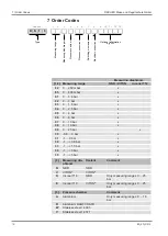
Страница 16: ...0 mbar x 83 0 400 mbar x 01 0 0 6 bar x 02 0 1 bar x 03 0 1 6 bar x 04 0 2 5 bar x 05 0 4 bar x 06 0 6 bar x 07 0 10 bar x 08 0 16 bar x 09 0 25 bar x 30 0 6 0 bar x 31 1 0 bar x 32 1 0 6 bar x 33 1 1...

Страница 17: ...nection in brass for 8 mm pipe CrNi steel 1 4571 26 Cutting ring connection in brass for 12 mm pipe CrNi steel 1 4571 28 Cutting ring connection in brass for 6 mm pipe Brass 29 Cutting ring connection...

Страница 18: ...ential pressure measuring and switch device DS13 The following can be used for example is a system is to be depressurized or taken out of operation for repairs or tests to disconnect differential pres...

Страница 19: ...FISCHER Mess und Regeltechnik GmbH Attachments 8 BA_EN_DS13 19 8 Attachments 8 1 SIL Certificate Fig 13 SIL_4479913759902...

Страница 20: ...8 Attachments FISCHER Mess und Regeltechnik GmbH 20 BA_EN_DS13 Fig 14 SIL_4479913759902...

Страница 21: ...FISCHER Mess und Regeltechnik GmbH Attachments 8 BA_EN_DS13 21 8 2 EU Declaration of Conformity Fig 15 CE_DE_DS13...

Страница 22: ...FISCHER Mess und Regeltechnik GmbH 22 BA_EN_DS13...

Страница 23: ...FISCHER Mess und Regeltechnik GmbH BA_EN_DS13 23...

Страница 24: ...lefelder Str 37a D 32107 Bad Salzuflen Tel 49 5222 974 0 Fax 49 5222 7170 www fischermesstechnik de info fischermesstechnik de Technische nderungen vorbehalten Subject to technical changes Sous r serv...

Отзывы: