


C1 Controllers and Transmitters
Instruction Manual
September 2009
6
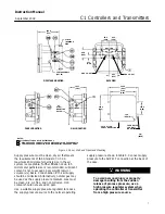
Panel Mounting
Cut a hole in the panel surface according to the
dimensions shown in figure 2. Remove the cap
screws (key 252), brackets (key 251), and vent
assembly (key 28). Slide the controller or transmitter
into the cutout and reattach the brackets. Tighten the
cap screw located in the center of each bracket to
draw the case snugly and evenly against the panel.
Reinstall the vent unless a remote vent will be used.
Wall Mounting
Drill four holes in the wall using the dimensions
shown in figure 2. In the bracket (key 251) are 8.7
mm (0.3438 inch) diameter holes. Back out the cap
screw located in the center of each bracket. (The
screws are used for panel mounting but are not
required for wall mounting.) If tubing runs through
the wall, drill holes in the wall to accommodate the
tubings. Figure 2 shows the pressure connection
locations in the back of the case.
Mount the controller to the bracket using the four cap
screws (key 252) provided. Attach the bracket to the
wall, using suitable screws or bolts.
Pipestand Mounting
Use a hammer and punch to knock out the blanks in
the two holes indicated in the back view of figure 2.
Attach the spacer spools (key 228) and the mounting
plate (key 213) to the controller with cap screws,
lock washers, and nuts (keys 215, 221, and 216).
Attach the controller to a 2
−
inch (nominal) pipe with
pipe clamps (key 250).
Actuator Mounting
Controllers specified for mounting on a control valve
actuator are mounted at the factory. If the instrument
is ordered separately for installation on a control
valve actuator, mount the instrument according to
the following instructions.
Mounting parts for the different actuator types and
sizes vary. Two typical actuator
−
mounting
installations are shown in figure 3; see the parts list
for parts required for the specific actuator type and
size involved.
Use a hammer and punch to knock out the blanks in
the two holes indicated in the back view of figure 2.
Attach the spacer spools (key 228) and the mounting
plate (key 213) to the controller with machine
screws, lock washers, and nuts (keys 215, 221, and
216).
Attach the mounting bracket to the actuator yoke
with cap screws (key 222) and, if needed, spacer
spools. On some designs, the mounting bracket is
attached to the actuator diaphragm casing rather
than to the yoke.
Pressure Connections
WARNING
To avoid personal injury or property
damage resulting from the sudden
release of pressure, do not install any
system component where service
conditions could exceed the limits
given in this manual. Use
pressure
−
relieving devices as required
by government or accepted industry
codes and good engineering practices.
All pressure connections on C1 Series instruments
are 1/4 NPT internal. Use 6 mm (1/4
−
inch) or 10 mm
(3/8
−
inch) pipe or tubing for supply and output
piping. The pressure connection locations are shown
in figure 2.
Supply Pressure
WARNING
Severe personal injury or property
damage may occur from an
uncontrolled process if the instrument
supply medium is not clean, dry,
oil
−
free and noncorrosive. While use
and regular maintenance of a filter that
removes particles larger than 40
micrometers in diameter will suffice in
most applications, check with an
Emerson Process Management field
office and industry instrument supply
medium quality standards for use with
hazardous gas or if you are unsure
about the proper amount or method of
air filtration or filter maintenance.


