


C1 Controllers and Transmitters
Instruction Manual
September 2009
29
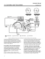
OUTER FLEXURE
(KEY 68)
MACHINE SCREW
(KEY 51)
BEAM
(KEY 39)
INNER FLEXURE
(KEY 67)
CANTILEVER SPRING
(KEY 8)
GE34726
−
B
E1068
MACHINE SCREW
(KEY 51)
BELLOWS SPACER
(KEY 34)
Figure 19. Beam/Cantilever Spring Assembly
d. Remove the gain adjustment bar (key 63). Flip
it over so it attaches to the opposite side of the
cantilever spring (key 8) as shown in figure 15
and re
−
attach.
e. Flip over the indicator scale (key 69, figure
18); install it and the proportional ban knob (key
73) as a unit. Snap in the lock spring (key 72).
f. Tighten down the spring adjustor (key 65) with
the bias spring (key 70) and washers (key 64)
until it stops against the gain adjustment bar
(key 63).
g. Turn the proportional band adjustment knob to
the 10 setting. If it cannot be turned, loosen the
spring adjustor (key 65).
6. Change the reversing block assembly (figure 15
or 16, key 37):
a. Remove the sealing screw (key 49, figure 23
or 24). Inspect the O
−
ring (key 77 located in the
recessed area under the sealing screw head.
Replace the O
−
ring if necessary.
b. Remove the reversing block screw (key 50,
figure 23 or 24) and reversing block assembly
(key 37). Inspect the O
−
rings (key 77) located in
the recessed area under the reversing block
screw head and between the reversing block
assembly and the calibration adjuster (key 36).
Replace these O
−
rings if necessary.
c. Position the reversing block assembly, with an
O
−
ring, on the calibration adjuster (key 36) so
that the nozzle is on the opposite side of the
beam (key 39) from which it was removed.
Position the reversing block hole in the calibration
adjuster. Install the reversing block screw (key
50) with an O
−
ring (key 77).
d. Install the sealing screw (key 49) with an
O
−
ring in the hole previously covered by the
reversing block assembly.
7. Check all connections for leaks with a
soap
−
and
−
water solution. Perform the appropriate
calibration procedures.
Relay Replacement
Key numbers used in this procedure are shown in
figure 21 or 22 except where indicated.
1. Shut off the supply pressure and process
pressure line(s) to the controller or transmitter.
2. Disconnect the tubing (key 24) from the relay.
3. Unscrew the output or supply pressure gauge
(key 2).
4. To remove the relay assembly, unscrew two
Phillips
−
head machine screws (key 29, not shown)
located behind the relay on the back of the case.
5. Remove the relay gasket (key 19, figure 21).
6. A new relay can be installed as a replacement. If
a new relay is being installed, continue with the next
step.


