


C1 Controllers and Transmitters
Instruction Manual
September 2009
24
preventative measures are not taken.
Preventative measures may include,
but are not limited to, one or more of
the following; Remote venting of the
unit, re
−
evaluating the hazardous area
classification, ensuring adequate
ventilation, and the removal of any
ignition sources. For information on
remote venting of this controller/
transmitter, refer to page 8.
D
Check with your process or safety
engineer for any additional measures
that must be taken to protect against
process media.
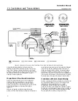
Replacing Gauges
Refer to figures 21 and 22 for key number locations
unless otherwise directed.
Three gauge configurations are available for C1
units.
D
Output and supply pressure indications
D
Output and process pressure indications
D
Output, process, and supply pressure
indications
One gauge type (key 2) is used for both output and
supply pressure indications when the gauges are
installed inside the controller case. Key 2 features a
1/8
−
inch connecting stem that matches the threaded
gauge boss extending from the relay base.
In some cases, a process pressure gauge (key 4)
covers the position of the internal supply pressure
gauge. The supply pressure gauge has been
removed and replaced with a pipe plug (key 15). The
pressure control block (key 10) is different to
accommodate a different control tubing assembly
(key 23) with a pressure connection (key 14) for a
process pressure gauge. If a supply pressure gauge
is required, a gauge with a 1/4
−
inch connecting stem
(key 3) must be mounted on the supply pressure
regulator.
CAUTION
Before performing this procedure, be
sure the replacement gauges are the
correct range so they are not damaged
by overpressure.
Note
Key 2 is used as both a supply gauge
and an output gauge on units without
a process pressure gauge. A quantity
of 2 is required for these units. On
units with a process pressure indicator
gauge (key 4), key 2 is used for the
output gauge. A quantity of 1 is
required for these units.
Use key 3 for supply pressure
indication when a process pressure
gauge is installed. Key 3 installs on the
supply pressure regulator.
1. Shut off the supply pressure and process lines to
the controller or transmitter.
2. Remove the gauge to be replaced:
D
Unscrew the output or supply gauge (key 2)
from the relay base.
D
Unscrew the process pressure gauge (key 4)
from the process connection (key 14).
D
Unscrew the supply gauge (key 3) from the
supply pressure regulator.
3. Coat the threads of the replacement gauge with a
sealant.
4. Screw the replacement gauge into the relay base,
process connection, or supply pressure regulator.
5. Check for leaks by applying the correct supply
pressure with the nozzle capped to produce full
output pressure.
Replacing Bourdon Tube
Refer to figure 23 for key number locations unless
otherwise directed.
1. Shut off the supply pressure and process lines to
the controller or transmitter.
2. Unscrew the machine screw (key 56) to
disconnect the link (key 16) and bearing (key 31)
from the beam (key 39). Be careful to avoid losing
the bearing (key 31). Washer(s) (key 62) for the
machine screw (key 56) are at times furnished for
insertion at the beam (key 39) connection to ensure
alignment of the connecting link (key 16).


