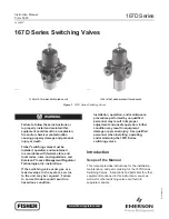


167D Series
7
4. Place the diaphragm assembly (key 16) on the body
(key 1) as shown in Figures 7 through 10. Push down
on the diaphragm assembly to make sure the valve
plug (key 57) strokes smoothly and approximately
1/16-inch / 1,6 mm.
Note
In step 5, if installing a control spring of
a different range, be sure to delete the
spring range originally appearing on the
label and indicate the new spring range.
5. Stack the control spring (key 17) and upper spring
seat (key 20) onto the diaphragm assembly (key 16).
6. Install the spring case assembly (key 7) on the body
(key 1) with the vent oriented to prevent clogging or
entrance of moisture. Install the six fl ange
screws (key 3) using a crisscross pattern and torque
to 15 to 30-inch-pounds / 1,7 to 3,4 N•m.
Note
On Types 167DS and 167DAS, lubricate
the adjusting screw (key 18) thread to
reduce galling of the stainless steel.
7. When all maintenance is complete, refer to
the Startup and Adjustment section to put the
switching valve back into operation and adjust
the pressure setting. Tighten the hexnut (key 19)
if used, and install the closing cap (key 33) if used.
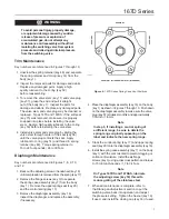
!
WARNING
To avoid personal injury, property damage,
or equipment damage caused by sudden
release of pressure or explosion of
accumulated gas, do not attempt any
maintenance or disassembly without fi rst
isolating the switching valve from system
pressure and relieving all internal pressure
from the switching valve.
Trim Maintenance
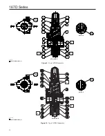
Key numbers are referenced in Figures 7 through 10.
1. Unscrew the spring retainer (key 48) and separate
the spring retainer and O-ring (key 14) from the
body (key 1).
2. Inspect the removed parts for damage and debris.
Replace any damaged parts. Apply a high
quality lubricant to the O-ring (key 50)
before reassembling.
3. To remove the valve stem (key 11) and valve plug
(key 57), grasp the end and pull it straight
out of the body (key 1). Inspect the parts for
damage and debris. Replace any damaged parts.
The valve stem and valve plug may be cleaned or
replaced. Types 167D and 167DS: If the soft seat
(key 15) was removed, make sure it is properly
snapped into place before installing the valve
stem. Apply a high quality lubricant to the O-ring
(key 50) before reinstalling the valve stem.
4. Install valve stem and valve plug by sliding the
valve stem through center of the seat (key 58)
until the valve plug contacts the seat. Apply
lubricant to O-ring (key 14) and thread in spring
retainer (key 48). Torque spring retainer to
18 to 22 foot-pounds / 24 to 30 N•m.
Diaphragm Maintenance
Key numbers are referenced in Figures 7, 8, 9, 10,
and 12.
1. Back out the adjusting screw or handwheel (key 18)
until compression is removed from the spring (key 17).
2. Remove the fl ange screws (key 3) to separate
the spring case assembly (key 7) from the body
(key 1). Remove the upper spring seat (key 20)
and the control spring (key 17).
3. Remove the diaphragm assembly (key 16),
inspect the diaphragm, and replace the assembly,
if necessary.
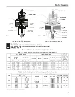
Figure 6.
167D Series Spring Case Vent Positions
POSITION 1 (ALIGNED WITH INLET) (STANDARD)
POSITION 3
POSITION 4
POSITION 2
GE31784