Fisher-Rosemount Design CV500 Скачать руководство пользователя страница 12

Design CV500

12

feeler gage to measure between the parts as shown in
figures 11 and 12, making certain the necessary
clearance exists. Compare the measured gap to the
clearance in table 5; proceed as follows:

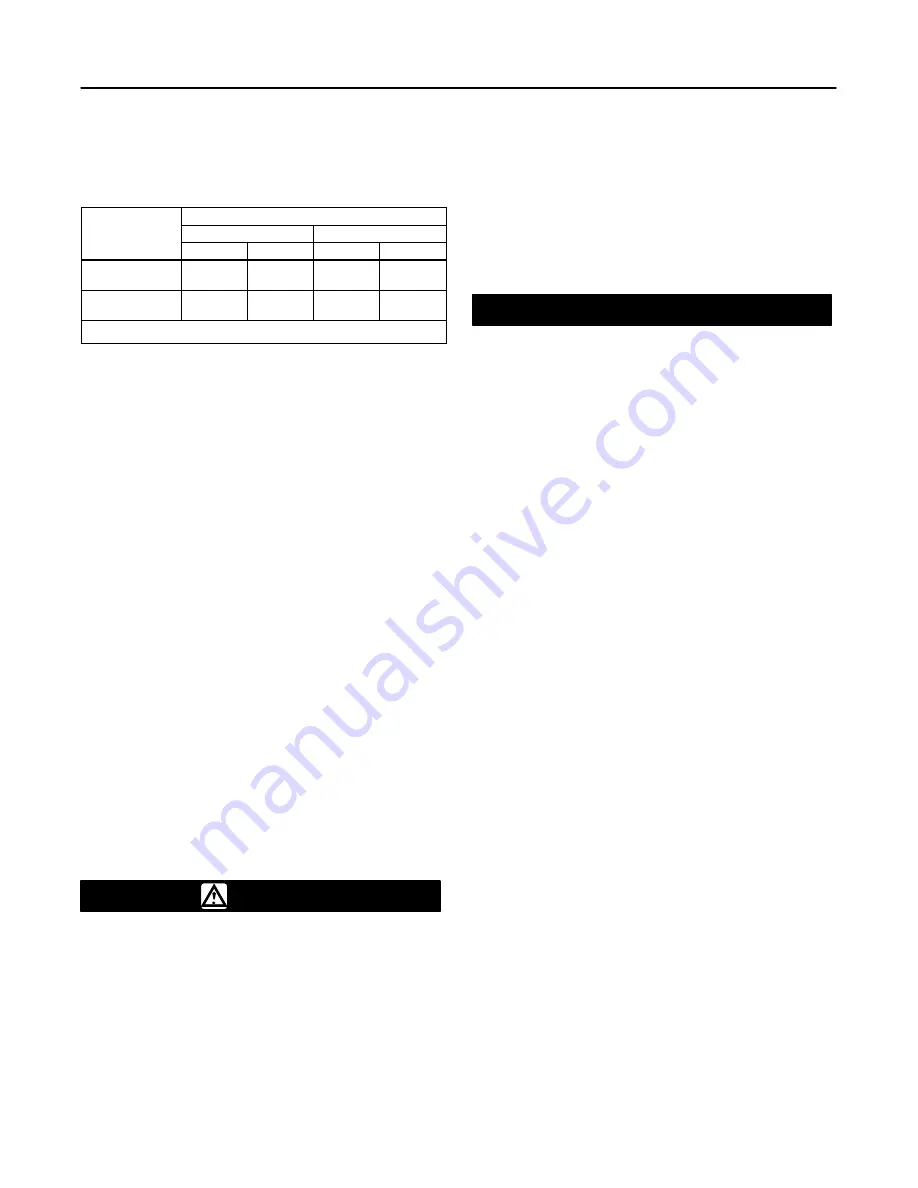
Table 5. Assembly Clearance

PROCESS

SEAT RING AND RETAINER CLEARANCE

PROCESS

TEMPERATURE

mm

Inches

TEMPERATURE

Minimum

Maximum

Minimum

Maximum

To 260

_

C

(500

_

F)

(1)

0.08

0.30

0.003

0.012

Over 260

_

C

(500

_

F)

(2)

0.20

0.30

0.008

0.012

1. Standard Trim
2. Special High Temperature Trim

D

If the measured clearance is within table values,

proceed to the next step.

D

If the measured gap is larger than the maximum,

tighten the retainer—apply more torque than that listed
in figure 7, if necessary, until the clearance is within
maximum and minimum values.

D

If the measured clearance is smaller than the

minimum, remove the retainer, seat ring, and face
seals, clean the parts, and reassemble so as to obtain
the necessary minimum clearance.

10.  Perform the Adjusting Actuator Travel procedure
and then install the control valve in the pipeline.

Replacing Ball, Shaft, and Bearings

Perform this procedure to replace the ball (key 2),
expansion pin (key 9), taper pin (key 10), drive shaft
(key 3), follower shaft (key 38), groove pins (key 39),
or bearings (keys 6 and 42). These parts are
independently replaceable; for example, installing a
new ball does not require replacing a reusable valve
shaft or expansion pin assembly. Key numbers refer to
figure 11 for 3 through 8-inch sizes and to figure 12 for
10 and 12-inch sizes unless otherwise indicated.

Disassembly

WARNING

To avoid personal injury resulting from
contact with edges of the V-notch ball
(key 2) and seat ring (key 4) during ball
rotation, stay clear of its edges when
rotating the ball. To avoid damage to
tools, valve parts, or other items
resulting from V-notch ball rotation,
keep tools and other property away from
the edges of the ball.

When the actuator is removed from the
valve, the ball/shaft assembly may
suddenly rotate, resulting in personal
injury or property damage. To avoid
injury or damage, carefully rotate the
ball/shaft assembly to a stable position
in the valve body after the actuator is
disconnected.

CAUTION

To avoid increased leakage, increased
valve component wear or possible
damage to the valve body (key 1), ball
(key 2), drive shaft (key 3), follower shaft
(key 38), and bearings (keys 6 and 42)
resulting from a sharp blow to the
actuator or valve parts, use a wheel
puller to separate the actuator parts
from the valve drive shaft.

Do not drive the actuator parts off the
valve drive shaft since this could move
the valve bearings, shafts, and ball away
from proper alignment, causing
improper seating of the ball. Such
misalignment may result in damage to
valve components if the valve is
returned to service without disassembly
and inspection of the ball alignment.

1.  Isolate the control valve from the line pressure,
release pressure from both sides of the valve body,
and drain the process media from both sides of the
valve. If using a power actuator, also shut-off all
pressure lines to the power actuator, release all
pressure from the actuator. Use lock-out procedures to
be sure that the above measures stay in effect while
you work on the equipment.

2.  Remove the actuator cover. Note the actuator
orientation with respect to the valve body and the lever
orientation with respect to the valve drive shaft (see
figure 3). Remove the lever but do not loosen the
actuator turnbuckle adjustment. Remove the actuator
mounting screws and nuts, and remove the actuator. If
necessary, refer to the actuator instruction manual for
assistance.

3.  With the valve body (key 1) out of the pipeline,
loosen the packing nuts (key 16). If the packing is to
be reused, do not remove it. However, Fisher
recommends that the packing be replaced whenever
the drive shaft is removed.

Содержание Design CV500

Страница 1: ...Direction 18 Changing Actuator Mounting Style 18 Parts Ordering 18 Parts Kits 18 Parts List 19 Introduction Scope of Manual This instruction manual provides installation operation maintenance and par...

Страница 2: ...ctuator rod opens valve body Shaft Diameters 2 and Approximate Weights See table 4 1 The pressure temperature limits in this manual and any applicable standard limitations should not be exceeded 2 Sha...

Страница 3: ...2 600 600 600 315 6 450 500 1 29_C 20_F for WCC steel valve body material 2 For hot water or steam service limit maximum temperature to 260_C 500_F 3 The pressure or temperature limits in this table...

Страница 4: ...e drive shaft horizontal and the Vee Ball closing in the downward direction for standard right hand mounting 6 Install the flange gaskets and insert the valve between the mating pipeline flanges For w...

Страница 5: ...R MOUNTING STYLE VALVE OPEN 1 2 3 4 NOTES 1 ARROW ON LEVER INDICATES DIRECTION OF ACTUATOR THRUST TO CLOSE VALVE 2 PDTC PUSH DOWN TO CLOSE PDTO PUSH DOWN TO OPEN 3 F FORWARD FLOW R REVERSE FLOW RIGHT...

Страница 6: ...DIN Qty Bolt Size Bolt Length mm Overall Length mm PN 10 40 4 M16 x 2 50 60 3 PN63 4 M20 x 2 5 60 73 3 PN100 4 M24 x 3 70 85 PN10 16 4 M16 x 2 50 60 4 PN25 40 4 M20 x 2 5 60 73 4 PN63 4 M24 x 3 70 85...

Страница 7: ...the retrofit kits listed in the parts kit sub section near the end of this manual Maintenance WARNING Avoid personal injury or property damage from sudden release of process pressure or bursting of pa...

Страница 8: ...ides of the valve If using a power actuator also shut off all pressure lines to the power actuator release all pressure from the actuator Use lock out procedures to be sure that the above measures sta...

Страница 9: ...ENT DOUBLE PACKING ARRANGEMENT PRESSURE SERVICE VACUUM SERVICE PRESSURE VACUUM SERVICE FOR PURGED BEARING CONSTRUCTION FOR PURGED BEARING CONSTRUCTION GRAPHITE RIBBON OR PTFE COMPOSITION PACKING PTFE...

Страница 10: ...ng or if seat ring inspection is necessary The actuator and valve must be removed from the pipeline however the actuator may remain mounted during this procedure Key numbers refer to figure 11 for 3 t...

Страница 11: ...re to a pneumatic actuator or other steps as appropriate When installing the seat ring keep hands tools and other objects out of the valve 1 Apply enough supply pressure to the actuator to open the ba...

Страница 12: ...otation keep tools and other property away from the edges of the ball When the actuator is removed from the valve the ball shaft assembly may suddenly rotate resulting in personal injury or property d...

Страница 13: ...groove pin key 39 that secures the ball key 2 to the follower shaft key 38 Remove the groove pin from the ball ear in the direction shown in figure 8 Using a pin punch and hammer firmly strike the cha...

Страница 14: ...inside the valve body on either side of the ball Only one of these two bearings is identified by key 6 The other bearing is located along the drive shaft on the other side of the V notch ball Figure 8...

Страница 15: ...for 10 and 12 inch sizes into the valve body and against the bearing stop 5 For 3 through 8 inch sizes inspect the drive shaft key 3 Insert the shaft end opposite the splined end into the packing box...

Страница 16: ...e drive shaft until the slash mark is vertical and facing out from the center of the shaft in the same direction as the ball seating surface See figure 10 Note When the valve drive shaft is correctly...

Страница 17: ...oved or disconnected from the valve and whenever the seat ring and retainer keys 4 and 5 are removed Too little actuator travel will increase shutoff leakage too much travel will cause excessive ball...

Страница 18: ...he procedure for changing actuator mounting style if the actuator must be repositioned and refer to the installation section to install the control valve assembly Be sure to reposition the flow direct...

Страница 19: ...ng Set Packing Set 1 1 106 Anti Extrusion Washer Anti Extrusion Washer 2 2 1 Order individual parts from the Parts List 2 Included in packing set key 105 Parts List Valve Body figures 11 and 12 1 Body...

Страница 20: ...aphite ribbon 1V949601652 Packing washer key 28 12B5927X012 14 Packing Follower 15 Packing Flange Stud 16 Packing Flange Nut 17 Packing Box Ring Use w all packing box constructions 316 SST 3 inch 16A6...

Страница 21: ...sign CV500 21 Figure 11 3 Through 8 Inch Design CV500 Valve 42B3374 A IL TCM SEAL DOUBLE PACKING SEALED BEARING NOTE MEASURE GAP HERE 1 APPLY LUB KEY NUMBERS NOT SHOWN ARE 28 30 31 33 36 37 130 AND 13...

Страница 22: ...Design CV500 22 Figure 12 10 and 12 Inch Design CV500 Valve 42B5286 A IL NOTE MEASURE GAP HERE 1 APPLY LUB KEY NUMBERS NOT SHOWN ARE 28 30 31 33 36 37 130 AND 131 DOUBLE PACKING SEALED BEARING...

Страница 23: ...E 1 inch 12B7053X012 1 1 2 2 inch 12B7402X012 3 inch 12B7438X012 4 inch 12B7450X012 6 8 inch 12B7462X012 Graphite 1 inch 13B8816X012 1 1 2 2 inch 13B8816X032 3 inch 13B8816X092 4 inch 13B8816X112 6 8...

Страница 24: ...Deep packing box 2 req d 1 inch 12B7062X012 1 1 2 2 inch 12B7412X012 3 inch 12B7448X012 4 inch 12B7460X012 6 8 inch not available Graphite Packing Standard packing box 1 inch 16A6082X012 1 1 2 2 inch...

Страница 25: ...A5187X012 19A3679X152 4 Sealed 19A3678X012 29A5188X012 6 Standard 1 19A4239X012 19A5190X012 19A4241X132 6 Sealed 19A4240X012 29A5191X012 8 Standard 1 19A3645X012 19A5193X012 19A3647X132 8 Sealed 19A36...

Страница 26: ...Design CV500 26...

Страница 27: ...Design CV500 27...

Страница 28: ...ed herein or their use or applicability We reserve the right to modify or improve the designs or specifications of such products at any time without notice Printed in U S A EFisher Controls Internatio...

Отзывы: