background image

39

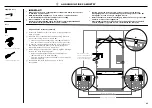
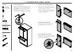
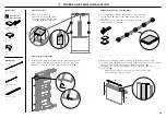
Attach the covers

1

  Open the French doors.  

Attach the top covers (

A

) firmly 

over the top studs, and the side 
covers (

B

) to the side brackets.

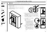
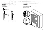
Attach the door side trims

2

  Install the side trims by inserting into the panel gaps on each 

side of the door(s) (

C

). Align the trim to the top of the door 

and press evenly into the panel gap until fully seated (

D

).

C

D

A

B

F

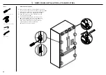
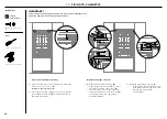
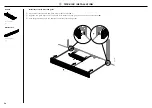
Attach the drawer top and side trims

3


Peel off two dual adhesive tabs and press them together 
to form a pair (

E

). Remove the adhesive backing on one 

side only.

4


Press firmly to the underside of the drawer top trim 
in the indicated locations (

F

).

5


Remove the remaining adhesive backing from the dual adhesive tabs. 

6


Locate the trim against the back surface of the panel and press down firmly. 
Ensure the trim is fully seated against the drawer surface (

G

).

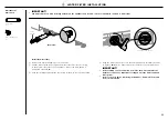
7


Install the side trims by inserting into the panel gaps on each side of 
the door(s) (

H

).


– Make sure the cabinet is centered to prevent the side trims 

from interfering with the cabinet.

G

H

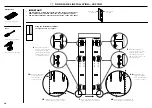
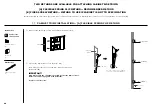
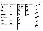
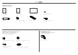
Internal box

C

Door / drawer 

trim install kit

Dual adhesive tabs  
(12)

Top cover  
(2)

Side cover 
(4)

External box

Door side trim  
(2)

Drawer side trim  
(2)

Drawer top trim  
(1)

@4

 COVERS AND TRIMS INSTALLATION

C

Содержание ACTIVESMART RS32A72

Страница 1: ...ACTIVESMART INTEGRATED FRENCH DOOR REFRIGERATOR FREEZER RS32A72 and RS36A72 models INSTALLATION GUIDE US CA 862212C 08 19...

Страница 2: ......

Страница 3: ...S 1 SAFETY AND WARNINGS 2 COMPONENTS 3 TOOLS 4 APPLIANCE AND CAVITY DIMENSIONS 5 CABINETRY OPTIONS 6 DOOR PANEL DIMENSIONS 7 CUSTOM DOOR PANEL INSTALLATION DIMENSIONS RS32A72 7 CUSTOM DOOR PANEL INSTA...

Страница 4: ......

Страница 5: ...se of ice and refer to the flushing instructions detailed in the installation section of this user guide installation guide If unpleasant taste or odor persists you may wish to fit a new filter cartri...

Страница 6: ...8 x 16 Mush Washer Twin Thread Philips Screw 8 x 16 Mush Washer Twin Thread Philips Screw M5x10 cross head screw 10 8Gx16 flat head screw 2 8 x 19 Countersunk Twin Thread Posi Screw 8Gx19 twin thread...

Страница 7: ...RS90 RS90AU models INSTALLATION GUIDE NZ AU GB IE HK SG IN 844219B 02 19 User guide 1 Service and Warranty 1 Installation guide 1 Collet locking clip 1 Water filter 1 Filter cartridge tool 1 Toe kick...

Страница 8: ...5 Pan Head Socket Screw M5 x 25 Pan Head Socket Screw M5 x 25 Pan Head Socket Screw M5 x 25 Pan Head Socket Screw M5x25 pan head socket screw 12x M5x25 pan head socket screw 12x M5x25 pan head socket...

Страница 9: ...ustment upwards RS32A RS36A CAVITY DIMENSIONS in mm in mm F Overall height of cavity 72 1829 72 1829 G Overall width of cavity 32 813 36 914 H Overall depth of cavity 25 635 25 635 I Minimum cabinetry...

Страница 10: ...ance with the cabinetry Proud installation Flush installation Note Drawings are only for reference and not the actual cavity width of the cabinetry FRAMED CABINETRY Aligns the appliance with the frame...

Страница 11: ...door panels 3 16 4 3 16 4 D Height of bottom drawer panel 23 7 16 596 23 7 16 596 e Height from bottom of product to top of drawer panel 27 1 2 698 27 1 2 698 f Width of bottom drawer panel 31 11 16 8...

Страница 12: ...PANEL REAR VIEW All measurements to be made from inner bottom corner For the second panel mirror and repeat dimensions using inner bottom corner as the reference point 2mm REF 10x Pilot holes recomme...

Страница 13: ...hment bracket for Fisher Paykel handles only If locating custom handle in the shaded area above ensure handle screw heads are counter sunk into back of panel to avoid interference with hanging bracket...

Страница 14: ...DE LH DOOR PANEL HINGE SIDE SIDE BRACKET HOLES SIDE BRACKET HOLES PRINT SPECIFICATION REVISIONS DRWN DATE CHKD ECN REV BJ 04 04 19 1 1 862946 GRAPHICS RS90 DOOR TEMPLATE TITLE DRAWN DATE SCALE 1 1 FIS...

Страница 15: ...T HOLES SIDE BRACKET HOLES FLIP FOR LEFT HAND DOOR AND DRAWER HOLES RH DOOR PANEL HINGE SIDE RH DOOR PANEL HANDLE SIDE SIDE BRACKET HOLES SIDE BRACKET HOLES RH DOOR PANEL BOTTOM EDGE DRAWER PANEL LEFT...

Страница 16: ...4 3 16 360 14 3 16 360 D Minimum door clearance to adjacent wall 115 full internal access 11 280 11 13 16 300 E Minimum door clearance to adjacent wall 90 reduced internal access 3 15 16 100 3 13 16 1...

Страница 17: ...nd the appliance and must not protrude from the back wall RS32A72 RS36A72 ELECTRICAL AND PLUMBING DIMENSIONS in mm A Overall height of supply area 4 5 16 110 4 5 16 110 B Overall width of supply area...

Страница 18: ...se and power cord ELECTRICAL SPECIFICATIONS Supply 115VAC 60Hz Service 10 amp circuit PLUMBING SPECIFICATIONS Supply 1 4 6mm comp Stainless steel braided hose Pressure min 22psi 150kPa max 120psi 827k...

Страница 19: ...ater fittings and water filter kits Installation kit and Miscellaneous items pack from inside the appliance Refer to Components pages 4 5 IMPORTANT Be careful when unpacking to prevent damage to the s...

Страница 20: ...nished return of solid material is required across the top and sides of the new or existing alcove Refer to the Appliance and cavity Dimensions page 7 prior to installation of the appliance 2 Check th...

Страница 21: ...f the minimum 60mm overlap cannot be achieved install a solid spacer to the wall stud behind the bracket IMPORTANT When positioning the appliance in the cabinetry ensure that the anti tip bracket over...

Страница 22: ...ront of the cabinetry close enough that you still have access behind for power and water connections A A D 2 Assemble the water fittings components onto the free end of the water tubing C Final water...

Страница 23: ...ly D and turn on the appliance 3 Attach the power cord clip to the back of your appliance and secure the excess power cord length onto the clip E When pushing the appliance into position take care not...

Страница 24: ...oors carefully 4 Loosely screw 1 2 turns M5x10 cross head screws into doors D Repeat this process for all appliance doors 1 2 turns D B 1 8 L O A C 2 Remove the left hinge end cap Hold onto the corner...

Страница 25: ...tional Install the top trim 1 Position the top trim on top of the top cover of the appliance A 2 Align the small screw hole of the top trim with the screw hole of the hinge bracket B Ensure the front...

Страница 26: ...A IMPORTANT Your appliance is fitted with front and rear rollers designed for moving the appliance in the forwards and backwards direction Avoid moving the appliance in a sideways direction as this m...

Страница 27: ...ols Ruler Powered driver optional Cross head screwdriver IMPORTANT Ensure all four corners of the appliance is supported firmly onto the floor to eliminate any movement DO NOT install the appliance on...

Страница 28: ...rom the handle holes 4 per each door panel 4 Align the handle holes with the door panel holes and secure with M5x25 pan head socket screws 4 per each door panel Note Door handle kit available and must...

Страница 29: ...g firmly until you feel it clip securely D On the external display enable the dispenser lock to prevent any water from dispensing during water connection To lock press the button for 4 seconds The LED...

Страница 30: ...at the sides of the doors A 2 Hang the door panel by inserting the M8 studs through the holes of the hanging bracket B 3 Slide the forks of the side brackets onto the screws of the door C 4 Screw the...

Страница 31: ...el turn the stud clockwise to raise or counter clockwise to lower the door panel A 3 Once satisfied with the alignment secure M8 studs with M8 washer and M8 nut B The top of the stud must remain below...

Страница 32: ...BRACKET HOLES DOOR PANEL SIDE BRACKET HOLES DOOR PANEL SIDE BRACKET HOLES DOOR PANEL SIDE BRACKET HOLES DOOR PANEL SIDE BRACKET HOLES DOOR PANEL SIDE BRACKET HOLES FLIP FOR LEFT DOOR PANEL LH DOOR PA...

Страница 33: ...DOOR PANEL SIDE BRACKET HOLES DOOR PANEL SIDE BRACKET HOLES DOOR PANEL SIDE BRACKET HOLES DOOR PANEL SIDE BRACKET HOLES DOOR PANEL SIDE BRACKET HOLES DOOR PANEL SIDE BRACKET HOLES FLIP FOR LEFT DOOR P...

Страница 34: ...E BRACKET HOLES DOOR PANEL SIDE BRACKET HOLES DOOR PANEL SIDE BRACKET HOLES DOOR PANEL HANGING BRACKET HOLES DOOR PANEL HANGING BRACKET HOLES DOOR PANEL SIDE BRACKET HOLES DOOR PANEL SIDE BRACKET HOLE...

Страница 35: ...kit available and must be purchased separately Refer to Components page 6 for more details Attach side brackets and straps E 6 Align the brackets and straps to the holes on the side of the panel and...

Страница 36: ...ng bracket B 3 Slide the forks of the side brackets onto the screws of the door C 4 Screw the M8 washer and nut to each stud D and re tighten the side screws E to fix the door panel do not fully tight...

Страница 37: ...remain below the top face of the door panel 4 Secure side bracket forks by tightening side screws C Repeat for all door panels Note For depth adjustment loosen the side screws adjust the panels and t...

Страница 38: ...back and forth movement Reattach the hinge end caps 3 Reattach the left hinge end cap B z z Align hinge cap to the appliance press and firmly slide the cap to the right z z Hold onto the corner of the...

Страница 39: ...d air in the water tank and filter system Refer to the user guide Operating instructions Automatic ice maker for more information Install the water filter 1 Remove the plastic wrapping of the new filt...

Страница 40: ...until it clips securely A 2 Align the top grille clips to the top plinth slots Ensure the top grille is in the correct orientation B 3 Push the grille firmly onto the appliance until the clips engage...

Страница 41: ...cking on one side only 4 Press firmly to the underside of the drawer top trim in the indicated locations F 5 Remove the remaining adhesive backing from the dual adhesive tabs 6 Locate the trim against...

Страница 42: ...et and discard Discard Top view of side trim engaged correctly in side trim bracket A Side trim bracket Side trim short lip B Internal box D Cabinet side trim install kit Side trim bracket 6 Spring cl...

Страница 43: ...side trim with brackets and spring clips against the alcove side wall with the shorter lip facing the bottom E IMPORTANT Ensure the side trim is positioned as high as it will go Push the side trim at...

Страница 44: ...asure 2 50mm from the front of cabinet from behind the doors to the front of the alcove and accurately mark a vertical line B 4 Align the bracket edge with the marked line and fix the bracket to the c...

Страница 45: ...the bottom bracket E Repeat for the remaining side trims IMPORTANT Each bracket has two engagement points for the trim to locate Ensure the trim is engaged at both points F Ensure there are no visual...

Страница 46: ...___________________________________________________________ Installer s Name _____________________________________________________________ Installer s Signature _______________________________________...

Страница 47: ...Mod les RS32A72 et RS36A72 GUIDE D INSTALLATION US CA 862212C 08 19 R FRIG RATEUR CONG LATEUR ENCASTRABLE ACTIVESMART PORTES FRAN AISES...

Страница 48: ......

Страница 49: ...PI CES 3 OUTILS 4 DIMENSIONS DE L APPAREIL ET DE LA CAVIT 5 OPTIONS D ARMOIRES 6 DIMENSIONS DE PANNEAU DE PORTE 7 DIMENSIONS D INSTALLATION DE PANNEAU DE PORTE SUR MESURE RS32A72 7 DIMENSIONS D INSTA...

Страница 50: ......

Страница 51: ...la ons et reportez vous aux instructions de rin age indiqu es dans la section d installation de ce guide d utilisation guide d installation Si le go t ou l odeur persiste vous pouvez remplacer le filt...

Страница 52: ...iture sup rieure de tiroir 1 Gabarit double face de panneau de porte 1 A Ensemble d assemblage de support antibasculement Support antibasculement 1 Cheville pour ma onnerie 4 10x40 Pan Head Philips Sc...

Страница 53: ...ABLE ACTIVESMART PORTES FRAN AISES Guide d utilisation 1 Service et garantie 1 Guide d installation 1 Clip de blocage de collet 1 Filtre eau 1 Outil de cartouche filtrante 1 Filtre de plinthe 1 Adapta...

Страница 54: ...is Non compris avec le produit Perceuse sans fil Tournevis pointe plate Scie m taux Tournevis cruciforme Couteau lame r tractable Ruban mesurer R gle Crayon Outils fournis Compris dans la bo te intern...

Страница 55: ...le haut RS32A RS36A DIMENSIONS DE LA CAVIT po mm po mm F Hauteur hors tout de la cavit 72 1829 72 1829 G Largeur hors tout de la cavit 32 813 36 914 H Profondeur hors tout de la cavit 25 635 25 635 I...

Страница 56: ...llation superpos e Installation encastr e Remarque Les illustrations sont fournies uniquement titre de r f rence et ne repr sentent pas la largeur de cavit r elle des armoires ARMOIRES AVEC MONTANT Al...

Страница 57: ...les panneaux de porte sup rieurs 3 16 4 3 16 4 D Hauteur du panneau de tiroir inf rieur 23 7 16 596 23 7 16 596 e Hauteur du bas de l appareil au sommet du panneau du tiroir 27 1 2 698 27 1 2 698 f L...

Страница 58: ...Toutes les mesures doivent tre effectu es partir du coin inf rieur int rieur Pour le deuxi me panneau utilisez les m mes dimensions sur l autre c t avec le coin inf rieur int rieur comme point de r f...

Страница 59: ...pour les poign es Fisher Paykel uniquement Si vous devez positionner une poign e sur mesure dans la zone ombrag e ci dessus assurez vous que les t tes de vis de la poign e soient renfonc es dans la p...

Страница 60: ...9 LH DOOR PANEL HANDLE SIDE LH DOOR PANEL HINGE SIDE SIDE BRACKET HOLES SIDE BRACKET HOLES PRINT SPECIFICATION REVISIONS DRWN DATE CHKD ECN REV BJ 04 04 19 1 1 862946 GRAPHICS RS90 DOOR TEMPLATE TITLE...

Страница 61: ...L HINGE SIDE SIDE BRACKET HOLES SIDE BRACKET HOLES FLIP FOR LEFT HAND DOOR AND DRAWER HOLES RH DOOR PANEL HINGE SIDE RH DOOR PANEL HANDLE SIDE SIDE BRACKET HOLES SIDE BRACKET HOLES RH DOOR PANEL BOTTO...

Страница 62: ...ement minimal de la porte par rapport au mur adjacent 115 acc s complet l int rieur 11 po 280 11 13 16 po 300 E D gagement minimal de la porte par rapport au mur adjacent 90 acc s r duit l int rieur 3...

Страница 63: ...ne pas d passer du mur arri re DIMENSIONS POUR LE RACCORDEMENT LECTRIQUE ET LA PLOMBERIE RS32A72 RS36A72 po mm po mm A Hauteur hors tout de la zone d alimentation 4 5 16 po 110 4 5 16 po 110 B Largeur...

Страница 64: ...n excluant la fiche 80 11 16 po 2050mm Tuyau d alimentation en eau 125 3 16 po 3180mm Tuyau d alimentation en eau 154 3 4 po 3930mm Distance maximale du tuyau et du cordon d alimentation SP CIFICATION...

Страница 65: ...d articles divers Reportez vous Pi ces pages 4 5 IMPORTANT D ballez votre produit avec soin pour viter d en endommager la surface Assurez vous que le produit est stable afin d viter tout basculement...

Страница 66: ...l alc ve existante ou nouvelle Reportez vous au tableau Dimensions de l appareil et de la cavit avant de proc der l installation du produit 2 V rifiez l alimentation lectrique Assurez vous de branche...

Страница 67: ...le positionnement du support antibasculement Placez le support de mani re ce que le rebord sup rieur de la surface de contact soit align avec la marque C 3 Marquez les emplacements des trous de vis su...

Страница 68: ...ordements d alimentation lectrique et d alimentation en eau l arri re A A D 2 Assemblez les raccords d alimentation en eau suivants l autre extr mit du tuyau d alimentation en eau C 3 Fixez le raccord...

Страница 69: ...rche 3 Fixez le clip de cordon d alimentation l arri re de votre r frig rateur puis ins rez l exc dent de cordon d alimentation dans le clip E Lors du d placement du r frig rateur en position veillez...

Страница 70: ...ez sans serrer 1 2 tours les vis cruciformes M5x10 dans les portes D R p tez cette proc dure pour toutes les portes de l appareil 1 2 tours D B L O A C 2 Retirez le capuchon d extr mit de la charni re...

Страница 71: ...niture sup rieure sur le dessus du couvercle sup rieur du produit A 2 Alignez le petit trou de vis de la garniture sup rieure avec le trou de vis du support de charni re B Assurez vous que la face ava...

Страница 72: ...re appareil est muni de roulettes avant et arri re qui facilitent le d placement de l appareil vers l avant et l arri re vitez de d placer l appareil lat ralement pour ne pas endommager les roulettes...

Страница 73: ...le Tournevis cruciforme 8 ALIGNEMENT DANS LES ARMOIRES Placez une r gle sur le devant du produit pour v rifier son alignement du haut vers le bas et de gauche droite B B C A Ajustement de la roulette...

Страница 74: ...poign e 4 pour chaque panneau de porte 4 Alignez les trous de poign e avec les trous du panneau de porte puis fixez l aide de vis t te creuse cylindrique M5x25 4 pour chaque panneau de porte Remarque...

Страница 75: ...Activez le verrouillage du distributeur sur l afficheur externe pour viter que l eau s coule du distributeur pendant le raccordement de l alimentation en eau Pour le verrouiller appuyez sur la touche...

Страница 76: ...les retirez pas sur les c t s des portes A 2 Suspendez le panneau de porte en ins rant les goujons M8 dans les trous du support d accrochage B 3 Glissez les fourches des supports lat raux sur les vis...

Страница 77: ...rer sous la face sup rieure du panneau de porte B A 5 5 Fixez les fourches de support lat ral en serrant les vis lat rales C R p tez pour tous les panneaux de portes Remarque Pour l ajustement en prof...

Страница 78: ...T HOLES DOOR PANEL SIDE BRACKET HOLES DOOR PANEL SIDE BRACKET HOLES DOOR PANEL SIDE BRACKET HOLES FLIP FOR LEFT DOOR PANEL LH DOOR PANEL HINGE SIDE LH DOOR PANEL HANDLE SIDE DRAWER PANEL HANDLE SIDE D...

Страница 79: ...L SIDE BRACKET HOLES DOOR PANEL SIDE BRACKET HOLES DOOR PANEL SIDE BRACKET HOLES DOOR PANEL SIDE BRACKET HOLES FLIP FOR LEFT DOOR PANEL 3 D placez le m me gabarit sur le c t droit du panneau de porte...

Страница 80: ...ACKET HOLES DOOR PANEL HANGING BRACKET HOLES DOOR PANEL HANGING BRACKET HOLES DOOR PANEL SIDE BRACKET HOLES DOOR PANEL SIDE BRACKET HOLES FLIP FOR LEFT DOOR PANEL DRAWER PANEL TOP EDGE LH DOOR PANEL H...

Страница 81: ...rte doit tre achet s par ment Reportez vous Pi ces page 6 pour plus de d tails Fixation des supports lat raux et des bandes lat rales E 5 Alignez les supports et les bandes sur les trous de chaque c t...

Страница 82: ...B 3 Glissez les fourches des supports lat raux sur les vis de la porte C 4 Vissez la rondelle et l crou M8 sur chaque goujon D puis resserrez les vis lat rales E pour fixer le panneau de porte ne serr...

Страница 83: ...support lat ralement selon les besoins 6 Desserrez le vis cruciforme M8x16 D afin que le support de verrouillage puisse glisser librement de l arri re vers l avant Glissez le support de verrouillage...

Страница 84: ...a droite reportez vous B Saisissez le coin du capuchon d extr mit puis poussez fermement vers le haut et la gauche pour enclencher le crochet de fixation Assurez vous que le capuchon soit au m me nive...

Страница 85: ...risonn dans le r servoir d eau et le syst me de filtration Reportez vous Instructions d utilisation Appareil gla ons automatique dans le guide d utilisation pour obtenir plus d informations Installati...

Страница 86: ...lidement A 2 Alignez les clips de la grille du haut avec les fentes de la plinthe sup rieure Assurez vous de placer la grille du haut dans le bon sens B 3 Poussez la grille fermement sur le produit ju...

Страница 87: ...etirez le support adh sif sur un c t seulement 4 Appuyez fermement sur le dessous de la garniture sup rieure de tiroir aux emplacements indiqu s F 5 Enlevez l endos adh sif restant des languettes adh...

Страница 88: ...la garniture lat rale enclench e correctement dans le support de garniture lat rale A Support de garniture lat rale Side trim languette courte B 40 1016mm 69 1753mm 10 254mm CHOISISSEZ L UNE DES DEUX...

Страница 89: ...orts et clips de fixation contre la paroi de l alc ve en orientant la languette courte vers le bas E IMPORTANT Assurez vous de positionner la garniture lat rale aussi haut que possible Poussez la garn...

Страница 90: ...lles n 8x16 C R p tez sur l autre c t IMPORTANT Assurez vous du positionnement ad quat du support pour viter l ajustement impr cis de la garniture lat rale ou la pr sence d espaces entre la garniture...

Страница 91: ...nitures lat rales restantes IMPORTANT Chaque support comporte deux points d enclenchement permettant d installer la garniture Assurez vous d enclencher la garniture aux deux points F Assurez vous qu i...

Страница 92: ...er facilement sans aucune r sistance caus e par les armoires proximit Assurez vous que la tige de limitation de charni re est ajust e pour une rotation de porte 90 Mod les Gla ons et eau uniquement As...

Отзывы: