5
STEP 8:
Install overflow tubing from overflow elbow on brine tank to floor drain. Tubing must be lower
than overflow elbow at all times to brine tank overflow in case of malfunction. DO NOT
CONNECT DRAIN LINE FROM SOFTENER CONTROL VALVE TO BRINE TANK
OVERFLOW.
STEP 9:
Place
control valve is in the “Service” position (time of day arrow pointing to the Service
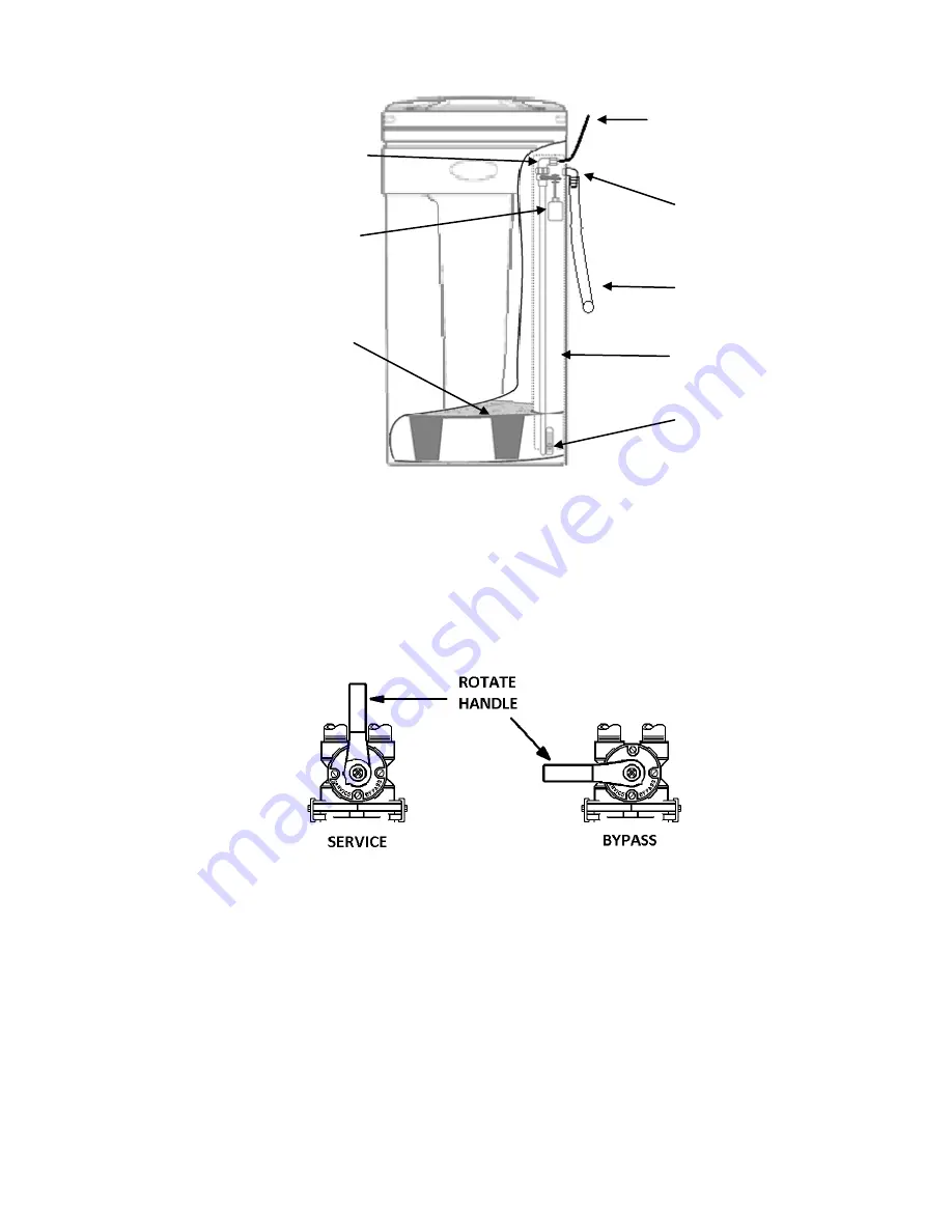
Position Indicator {see fig. 6, page 10}). Place bypass valve
in the “Bypass” position (refer to
Figures 4 below). Open main supply valve or turn on power to pump on private well systems.
STEP 10:
Rotate the Manual Regeneration Knob (see Fig. 5, page 7 & Fig. 6, page 10) to the Backwash
position.
STEP 11:
Refer to Figure 4 bypass valve operation. Rotate bypass lever of stainless steel bypass ¼ of
the way to Service allowing unit to fill slowly. Filling the mineral tank in this position will force
any trapped air to the drain. When all air has been purged from the system and only water is
running to the drain the tank is pressurized. F
ully open bypass valve to the “Service” position
and advance the control valve to the SERVICE position.
STEP 12:
Check for leaks and correct as necessary.
FIGURE 4: Stainless Steel Bypass Valve Operation
Safety Brine Valve
Brine Tank
Overflow Elbow
Salt Platform
Brine Well
Air Check
Safety Float
Brine Overflow
Drain Line
(Not included)
To Floor Drain
Brine Line To Brine
Valve on Control
Valve
FIGURE 3: Brine Tank
Содержание FECS Series
Страница 13: ...12 This page intentionally left blank ...
Страница 17: ...16 This page intentionally left blank ...
Страница 20: ...19 FS Time Clock Control Valve Breakdown ...
Страница 22: ...21 FSM Metered Control Valve Breakdown ...


